Rotary reeling and unreeling mechanism of round cutter die cutting machine

A technology of retracting and unwinding materials and circular knife molds, which is applied in thin material processing, metal processing, and winding strips, etc., which can solve the problems of long alignment time, large space occupation, and increased adjustment time of retracting and unwinding materials, and achieve fixed Good limit effect, convenient installation and adjustment, and good guiding effect

Pending Publication Date: 2018-08-24
DONGGUAN LINGYI PRECISION MFG TECH CO LTD
View PDF6 Cites 2 Cited by
  • Summary
  • Abstract
  • Description
  • Claims
  • Application Information

AI Technical Summary

Problems solved by technology

[0002] During the operation of the circular knife die-cutting machine, as the processing requirements change, the functional requirements of the axes are different. In ordinary machines, one axis has one function, and the distance between the axes is large. The disadvantages are: First, the same axis has a single function, realizing a The work needs to be equipped with multiple axes, the whole machine is complex, the production line is long, and it takes up a lot of space; secondly, due to the long distance between the functional axes, the time for changing materials is long, and the production efficiency is low; thirdly, the overall production line is long due to the distance between the axes. , It takes a long time to detect and monitor the position of the axis motion; Fourth, multiple axes are set within a long distance, the operation convenience is poor, and more labor is required; Fifth, multi-axis operation to achieve multiple actions requires multiple benchmarks, material rolls The conveying error is large, the cumulative error of processed products is large, the processing accuracy is low, and the alignment time of receiving and discharging materials is long, that is, the adjustment time is increased, and the working time is increased at the same time, which reduces the production efficiency.

Method used


Image

  • Rotary reeling and unreeling mechanism of round cutter die cutting machine
  • Rotary reeling and unreeling mechanism of round cutter die cutting machine
  • Rotary reeling and unreeling mechanism of round cutter die cutting machine

Examples


Embodiment Construction

[0038] The present invention will be described in further detail below in conjunction with the accompanying drawings. It should be noted that the words "front", "rear", "left", "right", "upper" and "lower" used in the following description refer to the directions in the drawings, and the words "inner" and "outer ” refer to directions towards or away from the geometric center of a particular part, respectively.

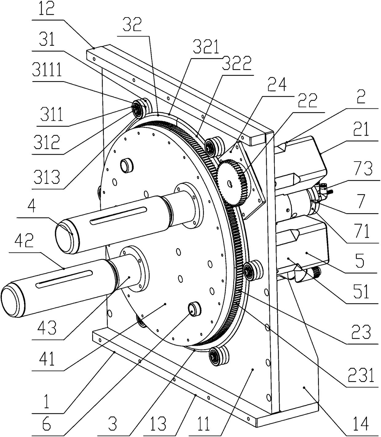
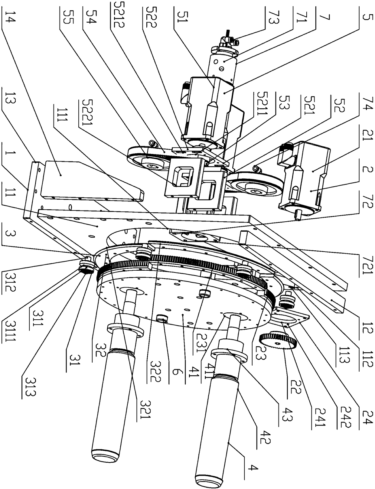
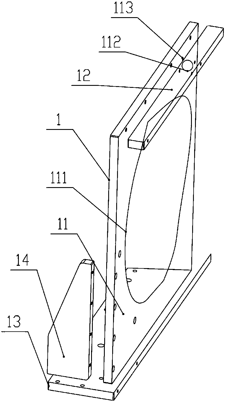
[0039] Figure 1 to Figure 9 A rotary feeding and unwinding mechanism of a circular knife die cutting machine according to an embodiment of the present invention is schematically shown. As shown in the figure, the device includes a support beam assembly 1, a first drive part 2, a guide assembly 3, a retractable assembly 4 and a second drive part 5,

[0040] The support beam assembly 1 is fixed on the circular knife machine. The support beam assembly 1 includes a main wall panel 11 set up vertically. The center of the main wall panel 11 is provided with a first throug...


PUM


Abstract

The invention discloses a rotary reeling and unreeling mechanism of a round cutter die cutting machine. The rotary reeling and unreeling mechanism of the round cutter die cutting machine comprises a supporting beam assembly. The supporting beam assembly comprises a main wallboard. A first motor is fixed to the rear side of the main wallboard. An outwards-extending shaft of the first motor is connected with a drive gear, and the drive gear is engaged with a driven gear. A guide assembly comprises a circle-ring-shaped circumferential track and a plurality of supporting guide pieces, wherein thecircumferential track cooperates with the multiple supporting guide pieces. A reeling and unreeling assembly comprises a round rotating base plate fixed to the front side of the driven gear. The frontside of the rotating base plate is internally and symmetrically connected with two air expanding shafts. Second motors drive a driven synchronous pulley. The tail ends of the air expanding shafts penetrate the driven gear, the circumferential track and first through holes to be connected with the driven synchronous pulley. The rotary reeling and unreeling mechanism has the beneficial effects thatreeling and unreeling functions are concentrated, the automatic and rapid material coil converting is achieved, and the production efficiency is high.

Description

technical field [0001] The invention relates to the field of circular knife die cutting machines, in particular to a rotary feeding and unwinding mechanism of a circular knife die cutting machine. Background technique [0002] During the operation of the circular knife die-cutting machine, as the processing requirements change, the functional requirements of the axes are different. In ordinary machines, one axis has one function, and the distance between the axes is large. The disadvantages are: First, the same axis has a single function, realizing a The work needs to be equipped with multiple axes, the whole machine is complex, the production line is long, and it takes up a lot of space; secondly, due to the long distance between the functional axes, the time for changing materials is long, and the production efficiency is low; thirdly, the overall production line is long due to the distance between the axes. , It takes a long time to detect and monitor the position of the ...

Claims


Application Information

Patent Timeline
Patent Type & Authority Applications(China)
IPC IPC(8): B65H75/24B65H16/04B65H18/08B65H18/02B26F1/38
CPCB65H16/04B65H18/026B65H18/08B65H75/243B26F1/38B65H2701/175B65H2701/1133
Inventor 周剑
Owner DONGGUAN LINGYI PRECISION MFG TECH CO LTD
Why Eureka
Try Eureka