
Device for detecting road flatness

A detection device and a technology for flatness, applied in the field of road flatness detection equipment, can solve problems such as unreliable test results, and achieve the effects of easy implementation, simple implementation, and improved accuracy

Active Publication Date: 2019-03-08
TSINGHUA UNIV +1
View PDF4 Cites 9 Cited by
  • Summary
  • Abstract
  • Description
  • Claims
  • Application Information

AI Technical Summary

Problems solved by technology

However, due to the limitations of the accelerometer, the laser cross-section flatness meter usually needs to be measured at a high speed and a constant speed, and the test results at a low speed and a variable speed state are unreliable

Method used


Image

  • Device for detecting road flatness
  • Device for detecting road flatness
  • Device for detecting road flatness

Examples


Embodiment Construction

[0022] The following describes in detail the embodiments of the present invention, examples of which are illustrated in the accompanying drawings, wherein the same or similar reference numerals refer to the same or similar elements or elements having the same or similar functions throughout. The embodiments described below with reference to the accompanying drawings are exemplary, and are intended to explain the present invention and should not be construed as limiting the present invention.

[0023] The following describes a road smoothness detection device according to an embodiment of the present invention with reference to the accompanying drawings.

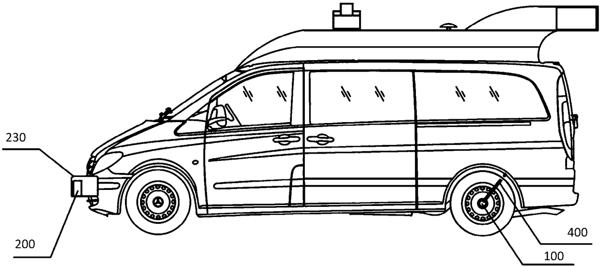
[0024] figure 1 It is a schematic structural diagram of a road flatness detection device according to an embodiment of the present invention.

[0025] like figure 1 As shown, the road flatness detection device 10 includes: a distance measurement module 100 , an elevation measurement module 200 and a detection module 300 . ...


PUM


Abstract

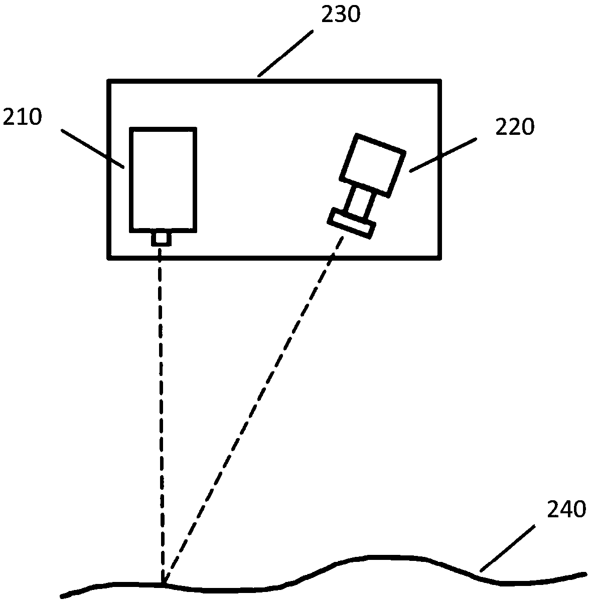
The invention discloses a device for detecting road flatness. The device comprises a distance measurement module, a height measurement module, and a detection module, wherein the distance measurementmodule is arranged at a concentric position of a wheel axle of a left wheel and / or a right wheel on the rear side of a vehicle and is used for detecting a current driving distance of the vehicle; theheight measurement module is arranged on a wheel track tape position of the left wheel and / or the right wheel on the front side of the vehicle, and comprises a line laser used for vertically emittinglaser rays to the road surface, and a three-dimensional camera used for capturing scattered laser rays and performing height extraction on the captured laser rays so as to acquire height data of a road section; and the detection module is used for acquiring a detection result of road flatness according to the height data of the road section. According to the device disclosed by the invention, thecombination of the line laser and the three-dimensional camera is utilized to accurately measure and acquire the detection result of road flatness, and the device is suitable for measurement at various speeds and meets the requirements of urban road flatness detection, so that the accuracy, applicability and reliability of road flatness detection can be effectively promoted, and the detection is simple and can be easily realized.

Description

technical field [0001] The invention relates to the technical field of road detection, in particular to a road flatness detection device. Background technique [0002] Road smoothness is the main index of road performance evaluation, which reflects the comfort and driving quality of road surface, and is of great significance in the evaluation of road service performance. The main index of the existing roughness evaluation is IRI (International Roughness Index, International Roughness Index). IRI is a statistical index based on 1 / 4 vehicle model. The ratio of the cumulative vertical displacement of the rack system to the distance traveled by the vehicle. In practical solutions, it is often calculated by numerical methods. The current flatness detection mainly adopts the section detection method, and calculates the IRI by obtaining the relative elevation of the road longitudinal section. Among them, the laser section flatness tester has been widely used as a rapid detection...

Claims


Application Information

Patent Timeline
Patent Type & Authority Applications(China)
IPC IPC(8): E01C23/01
CPCE01C23/01
Inventor 呙润华田涛
Owner TSINGHUA UNIV
Learn More