
Blister subsequent die cutter cutting forming device

A molding device and mold knife technology, applied in the direction of metal processing, etc., can solve problems such as product quality impact, time delay, and high labor intensity, and achieve the goal of improving personal and equipment safety, reducing strength and personal safety, and reducing labor intensity. Effect

Pending Publication Date: 2019-03-08
ANHUI JINZHENG PLASTIC
View PDF0 Cites 2 Cited by
  • Summary
  • Abstract
  • Description
  • Claims
  • Application Information

AI Technical Summary

Problems solved by technology

[0013] Poor quality stability: Since the mold knife is directly placed on the transmission belt, when passing through the roller pressure cutting, it will be rubbed by the conveyor belt and the strong rolling friction of the roller, which will aggravate the wear of the bottom of the mold knife, gradually lose parallelism, and lose After the parallelism, the die edge loses the vertical force, the product cutting accuracy will be affected, and the product quality will also be affected, which may eventually lead to the damage of the die edge and unnecessary waste
[0014] Low production capacity: Since the operator needs to walk back and forth to work, and also needs to bend down to pick up the cut products, it is very time-consuming and has a great impact on production capacity
[0015] Either way, there are disadvantages such as low production capacity, no safety guarantee for people and equipment, high labor intensity, high energy consumption, shortened life of mold knives, and unguaranteed product qualification rate and quality.

Method used


Image

  • Blister subsequent die cutter cutting forming device
  • Blister subsequent die cutter cutting forming device
  • Blister subsequent die cutter cutting forming device

Examples


Embodiment Construction

[0046] The present invention will be described in further detail below in conjunction with the accompanying drawings and specific embodiments.

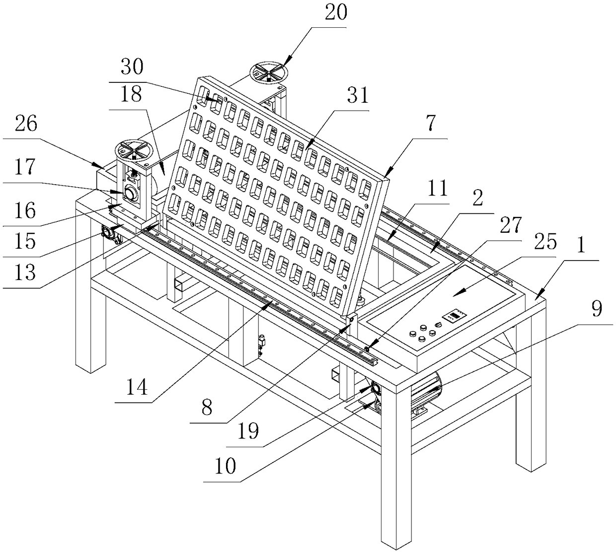
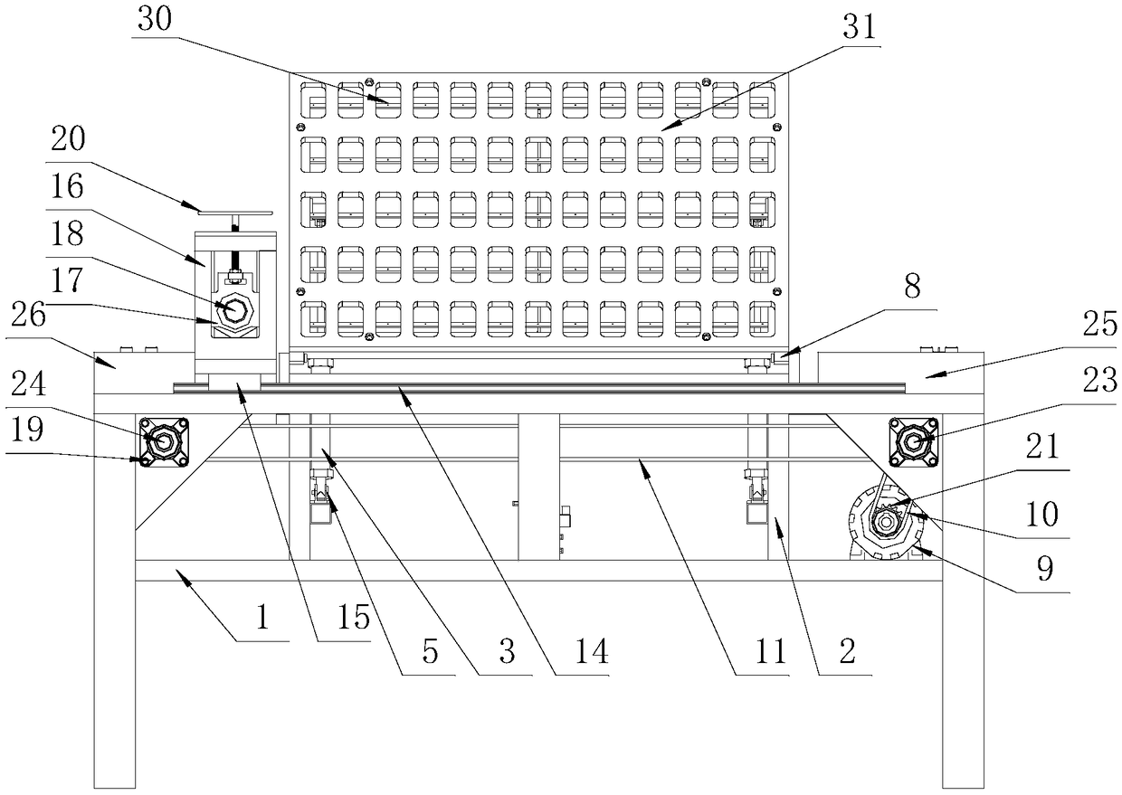
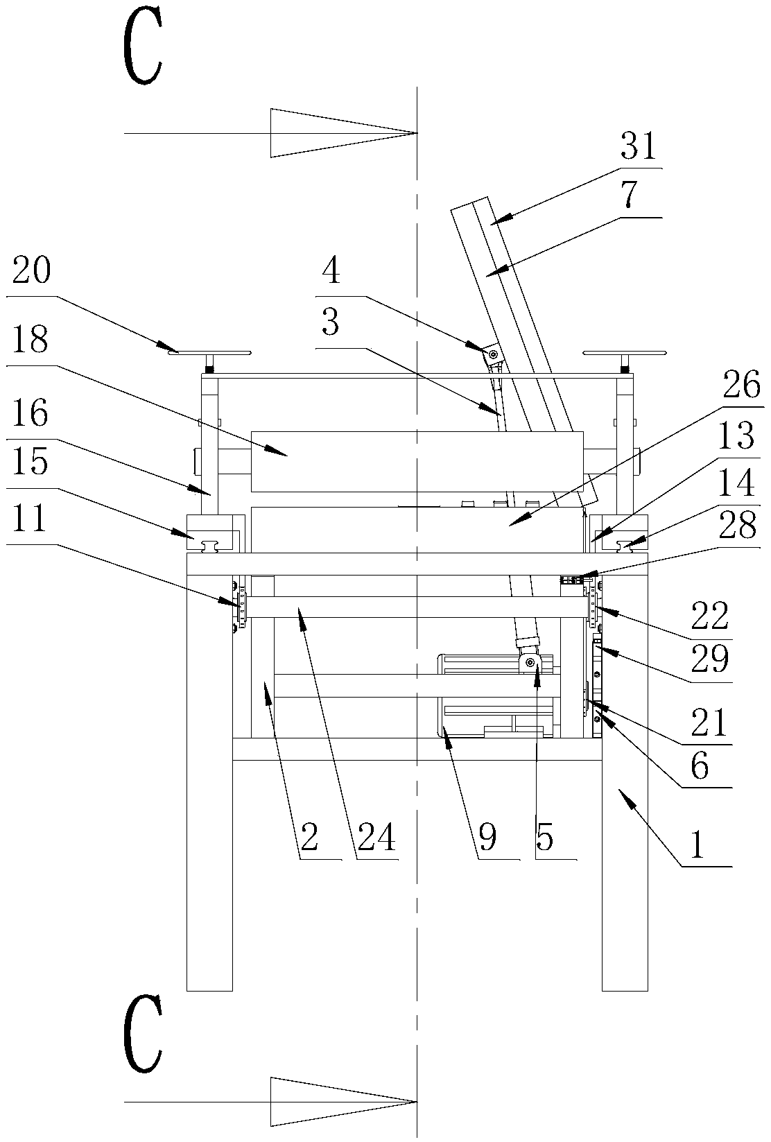
[0047] see Figure 1 to Figure 14 : The embodiment of the present invention provides a kind of mold knife cutting molding device after blistering, comprising outer bracket structure 1, inner bracket structure 2, pressure roller movement mechanism, mold knife turning mechanism, automatic blowing mechanism and electric control mechanism, inner The support structure 2 is inside the outer support structure 1; the outer support structure 1 is a frame welded by metal square pipes and channel steel, and the outer support structure 1 is provided with a pressure roller movement mechanism and an electric control mechanism; The inner support structure 2 is a frame welded by metal square pipes and channel steels. This frame is inside the outer support structure 1. The inner support structure 2 includes a mold knife turning mechanism and an automa...


PUM


Abstract

The invention discloses a blister subsequent die cutter cutting forming device, which comprises an outer bracket structure, an inner bracket structure, a press roller motion mechanism, a die cutter overturning mechanism, an automatic air blowing mechanism and an electronic control mechanism. The inner bracket structure is located in the outer bracket structure; the outer bracket structure is provided with the press roller motion mechanism and the electronic control mechanism; and the inner bracket structure comprises the die cutter overturning mechanism and the automatic air blowing mechanism.The blister subsequent die cutter cutting forming device has the beneficial effects that the automation degree is high, terminal collision protection is provided, thus the labor intensity of an operator is relieved, the maximum service life of a die cutter is guaranteed, the pass rate of product cutting is also guaranteed, the production capacity is improved, energy consumption is lowered, and the safety of persons and equipment is guaranteed.

Description

technical field [0001] The invention relates to the technical field of post-molding deep processing of plastic sheet packaging, in particular to a cutting and forming device for post-blister mold knife cutting. Background technique [0002] At present, there are mainly two ways of cutting and forming equipment for mold knife cutting after blistering: [0003] The first one is to use hydraulic machinery for stamping and cutting. The main disadvantages of this equipment are: [0004] Lower production capacity: first stamp the processed large piece of forming frame material into a small frame material of about 20X20 cm, then manually collect it for temporary storage, and finally manually stack several layers of the small frame material and place it in the die knife for stamping and cutting again, and manually take it out again One-time stamping and automatic separation of a whole sheet or a large area is not possible. Due to the cumbersome process, the production capacity is l...

Claims


Application Information

Patent Timeline
IPC IPC(8): B26F1/38B26D7/18B26D7/22B26D7/26B26D7/32B29C51/26
CPCB26D7/1854B26D7/22B26D7/2614B26D7/32B26F1/38B29C51/264Y02P70/10
Inventor 黄晓路葛连斌樊莉莉
Owner ANHUI JINZHENG PLASTIC
Learn More