
A paint spraying device for building construction

A technology of building construction and spraying device, applied in spraying device, liquid spraying device, construction and other directions, can solve the problems of uneven spraying and user inconvenience, and achieve the effect of ensuring spraying quality, stirring evenly, and avoiding deposition

Inactive Publication Date: 2020-05-15
许建生
View PDF1 Cites 0 Cited by
  • Summary
  • Abstract
  • Description
  • Claims
  • Application Information

AI Technical Summary

Problems solved by technology

[0004] However, the above-mentioned technical solution also has the following problems: the above-mentioned technical solution uses the existing spraying mechanism, so there is a problem of uneven spraying, which brings inconvenience to the user

Method used


Image

  • A paint spraying device for building construction
  • A paint spraying device for building construction
  • A paint spraying device for building construction

Examples


Embodiment 1

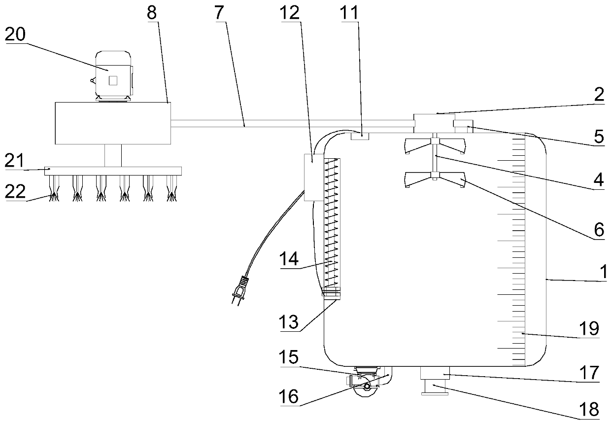
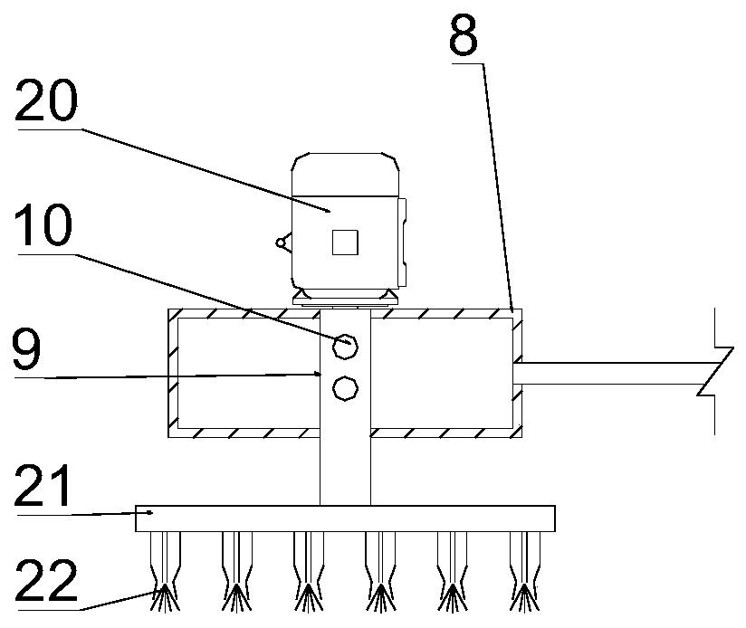
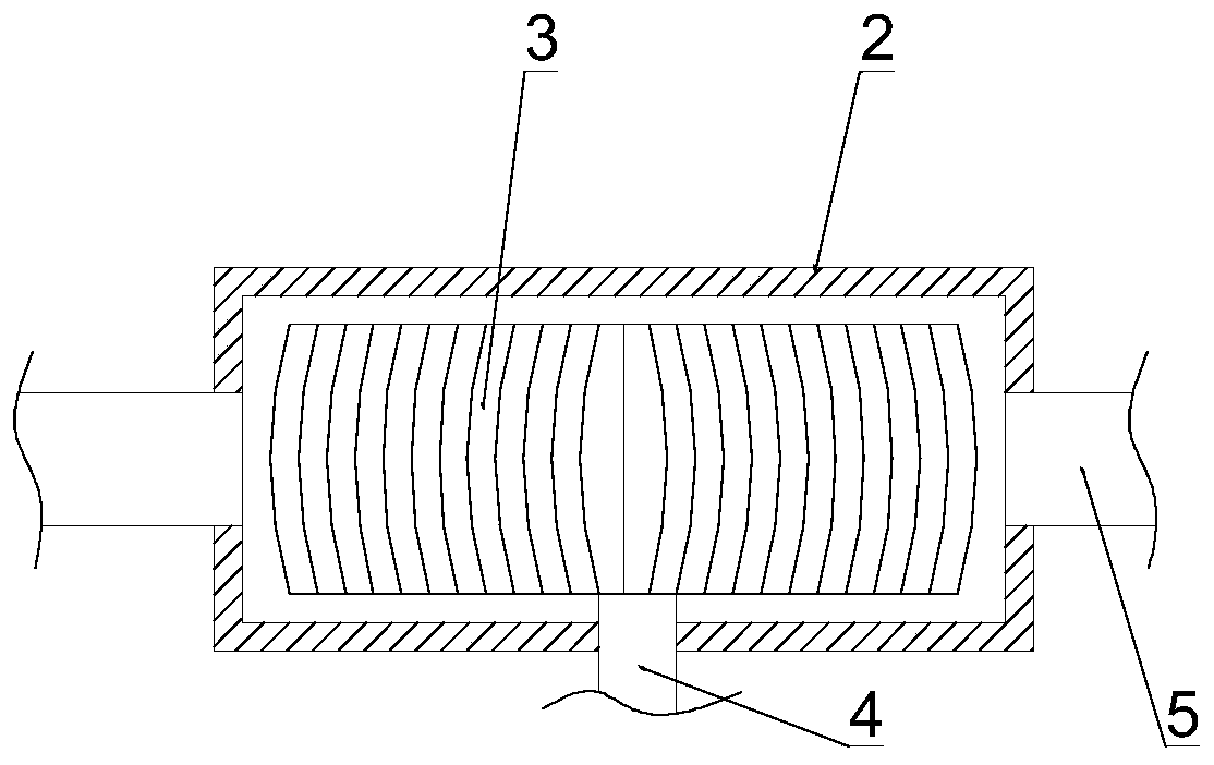
[0026] A kind of paint spraying device for building construction, please refer to figure 1 and 2 , comprising a paint tank 1, the upper part of the paint tank 1 is fixedly connected with a housing 2, the inside of the housing 2 is provided with a rotating wheel 3, and the mounting hole of the rotating wheel 3 is fixedly connected with a wheel that is rotatably connected with the side wall of the housing 2 Rotating cylinder 4, rotating cylinder 4 extends to the inside of paint tank 1 and several turning plates 6 are installed on rotating cylinder 4, one side of the inside of housing 2 passes through intermediate pipeline 5 and the inner upper part of paint tank 1 Connected, the other side of the inside of the housing 2 is connected with a hose 7, a negative pressure pump 15 is installed on the bottom of the paint tank 1, and the gas outlet of the negative pressure pump 15 is connected to the inside of the paint tank 1 through a communication pipe 16. The side phase is connecte...

Embodiment 2

[0029] On the basis of Example 1, please refer to figure 1 and 3 , the lower side wall of the paint tank 1 is fixedly connected with a supplementary pipeline 17, the inner wall of the supplementary pipeline 17 is bonded with a soft rubber layer, and a sealing rod 18 is movable embedded in the soft rubber layer, and the negative pressure pump 15 is equipped with a power cord and The switch, the paint box 1 is made of transparent material, and the display scale value 19 is printed on the paint box 1, and the upper wall of the housing 2 is respectively equipped with sealed bearings, and the rotating cylinder 4 is installed in the mounting hole of the sealed bearing, and the upper wall of the paint box 1 A temperature sensor 11 is installed on the side inner wall, a ceramic body 13 is fixedly connected to the side wall of the paint box 1, a heater 14 is installed in the ceramic body 13, a PLC controller 12 is installed on the surface of the paint box 1, and the diameter of the tur...


PUM


Abstract

The invention discloses a coating spraying device for building construction, and relates to the technical field of building construction. The coating spraying device comprises a coating tank, a shellis fixedly connected to the upper part of the coating tank, a rotating wheel is arranged in the shell, a mounting hole of the rotating wheel is fixedly connected with a rotating cylinder rotatably connected with the side wall of the shell, the rotating cylinder extends into the coating tank, and a plurality of material overturning plates are mounted on the rotating cylinder; one side in the shellcommunicates with the upper part in the coating tank through a middle pipeline, the other side in the shell communicates with a hose, and a negative pressure pump is mounted on the lower part of the coating tank. A servo motor drives a hollow pipe to rotate, thus a tank body drives spraying heads to rotate, the spraying area is more even, and the spraying quality is improved; and coating with a certain flow speed passes through the rotating wheel and then enables the rotating wheel to rotate, thus the rotating cylinder drives the material overturning plates to rotate, the coating is stirred, the coating deposition problem is avoided, and the coating is stirred evenly.

Description

technical field [0001] The invention relates to the technical field of building construction, in particular to a paint spraying device for building construction. Background technique [0002] Paint is coated on the surface of the object to be protected or decorated, and can form a continuous film firmly attached to the object to be coated. Among them, all paints that use water as a solvent or as a dispersion medium are called water-based paints. The last relatively new type of paint is widely used in interior and exterior wall paint, metal paint, automotive paint and other fields. In the use of water-based paint, spraying machinery and equipment are usually required, but the existing spraying machinery and equipment are complex in structure and expensive, and are not suitable for use in small and medium-sized production. [0003] In the Chinese patent whose authorized announcement number is CN205128275U, a water-based paint spraying equipment is disclosed, including an air ...

Claims


Application Information

Patent Timeline
Patent Type & Authority Patents(China)
IPC IPC(8): B05B15/25B05B9/04E04F21/08
CPCB05B9/0403B05B15/25E04F21/08
Inventor 许建生
Owner 许建生
Learn More