A business method of autonomous network and autonomous network
A network and autonomous cloud technology, applied in the field of communication, can solve the problems of consumers displaying video communication services, unable to "guarantee" the quality of network transmission, etc., and achieve the effects of easy scalability, stable rate, controllable delay, and improved stability
- Summary
- Abstract
- Description
- Claims
- Application Information
AI Technical Summary
Problems solved by technology
Method used
Image
Examples
example 1
[1269] Example 1. Single autonomous cloud network access
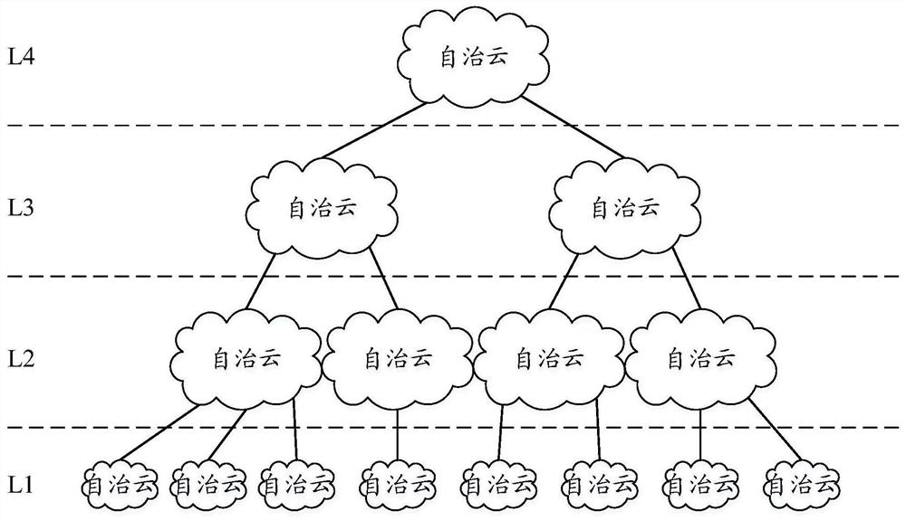
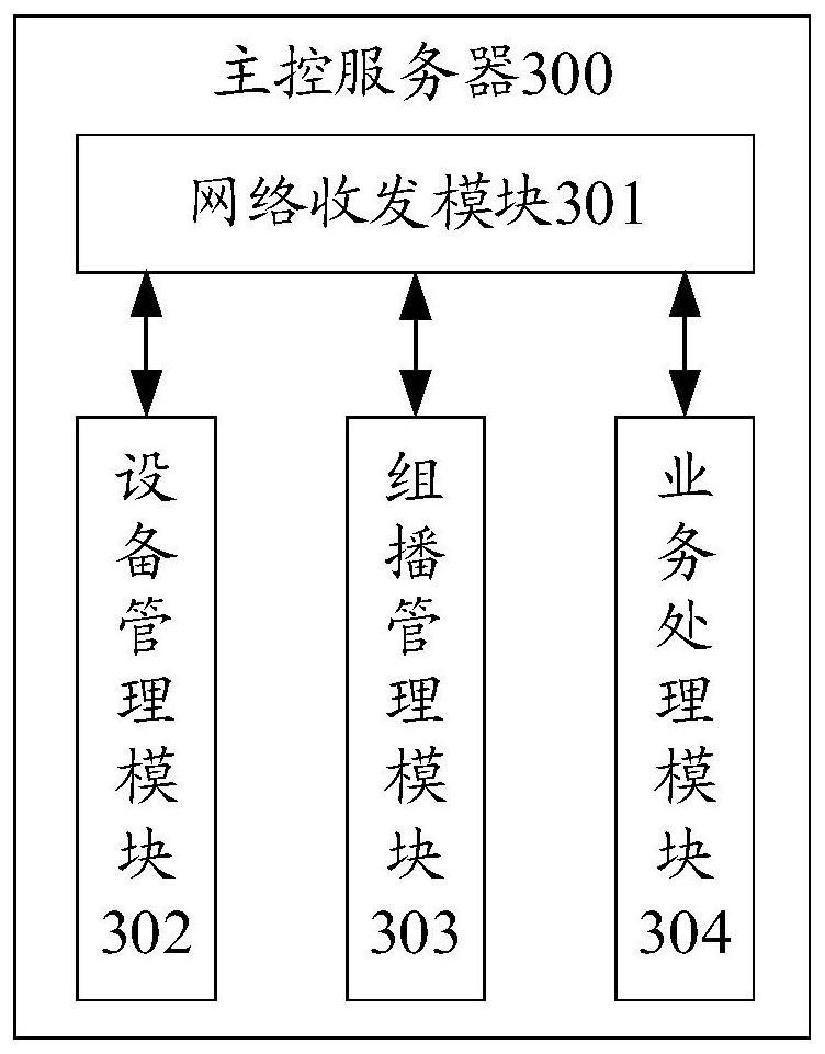
[1270] like Figure 25 As shown, it is assumed that the autonomous cloud C2 is located at the second layer in the autonomous network. For the sake of simple description, the border sub-control server and the border router are ignored, the main control server A2 and the terminal sub-control server B21, the terminal sub-control server B22 and the terminal sub-control server B23 is connected to the same switching network, the terminal sub-control server B21 is connected to the same switching network as the terminal T21 and terminal T22, and the terminal sub-control server B22 is connected to the same switching network as the terminal T23 and terminal T24, and the terminal sub-controller B22 is connected to the same switching network. The server B23 is connected to the same switching network as the terminal T25 and the terminal T26.
[1271] S1, device initialization.
[1272] S11, the main control server A2 is powered o...
example 2
[1406] Example 2. Multi-autonomous cloud network access
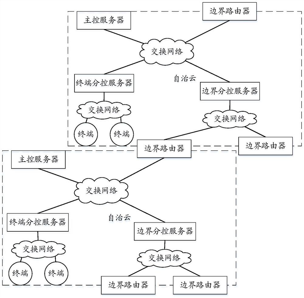
[1407] like Figure 26 As shown, it is assumed that the autonomous cloud C2 is located at the second layer of the autonomous network, and the autonomous cloud C3 is located at the third layer of the autonomous network, and the autonomous cloud C2 is connected with the autonomous cloud C3 multiplexing the border router M21. For simple description, the terminal is ignored.
[1408] In the autonomous cloud C2, the main control server A2, the terminal sub-control server B21, the border sub-control server B22, and the border router M21 are connected in the same switching network.
[1409] In the autonomous cloud C3, the main control server A3, the terminal sub-control server B31, the border sub-control server B32, and the border router M31 are connected to the same switching network, and the border sub-control server B32, the border router M21, and the border router M22 are connected to another. in the switching network.
...
example 3
[1537] Example 3. Configuring a multicast link in a single autonomous cloud (no multicast address replacement inside the autonomous cloud)
[1538] like Figure 25 As shown in the figure, it is assumed that the autonomous cloud C2 is located at the second layer of the autonomous network. For the sake of simple description, the border sub-control server and the border router are ignored, the main control server A2 and the terminal sub-control server B21, the terminal sub-control server B22, and the terminal sub-control server B23 The terminal sub-control server B21 is connected to the same switching network as the terminal T21 and the terminal T22, and the terminal sub-control server B22 is connected to the terminal T23 and the terminal T24 in the same switching network, and the terminal sub-control server B22 is connected to the same switching network. B23 is connected to the same switching network as the terminal T25 and the terminal T26.
[1539] 1. Create a data source for...
PUM
 Abstract
Description
Claims
Application Information
 - R&D
- Intellectual Property
- Life Sciences
- Materials
- Tech Scout
- Unparalleled Data Quality
- Higher Quality Content
- 60% Fewer Hallucinations
Browse by: Latest US Patents, China's latest patents, Technical Efficacy Thesaurus, Application Domain, Technology Topic, Popular Technical Reports.
© 2025 PatSnap. All rights reserved.Legal|Privacy policy|Modern Slavery Act Transparency Statement|Sitemap|About US| Contact US: help@patsnap.com


