
Automatic focusing method and device

An automatic focus and focus position technology, applied in installations, instruments, microscopes, etc., can solve the problems of short working distance of objective lens, high algorithm cost, inability to focus in real time, etc., to simplify optical path design, simple signal calculation and processing, fast, accurate and automatic. The effect of focusing

Inactive Publication Date: 2019-03-05
MGI TECH CO LTD +1
View PDF5 Cites 1 Cited by
  • Summary
  • Abstract
  • Description
  • Claims
  • Application Information

AI Technical Summary

Problems solved by technology

However, the depth of field of the objective lens with high magnification and large numerical aperture is very small, usually only a few microns, and the fluctuation of the sample surface has a great impact on imaging, so a fast and high-precision real-time autofocus device is required
[0003] At present, the autofocus methods used in microscopes and gene sequencers are roughly divided into two types. One is to use image analysis methods to find the best focal plane. This method requires post-image processing. The disadvantage is that it is slow, and the cost of hardware and algorithms is high. , unable to focus in real time
Especially for gene sequencers, the chip has quenching properties, and it is not possible to take multiple pictures; the other is to use laser triangulation ranging method, the disadvantage of which is low accuracy
[0004] In the prior art, there is a focusing method that uses different algorithms to post-process the images after collecting multiple images, and then determines the position of the focal plane. The disadvantages of this method are high cost, slow speed, and inability to focus in real time.
[0005] Another focusing method in the prior art is to measure and calculate the vertical distance between the objective lens and the sample by a distance measuring sensor to realize automatic focus adjustment. The distance measuring sensor used in this method is located on the side of the objective lens. Short, the measuring beam cannot approach the objective lens
This method is actually delayed focusing, and the accuracy is not high

Method used


Image

  • Automatic focusing method and device
  • Automatic focusing method and device
  • Automatic focusing method and device

Examples


Embodiment 1

[0043] In this embodiment, an automatic focusing device is provided, and the automatic focusing device is used for real-time automatic focusing on instruments such as microscopes and gene sequencers.

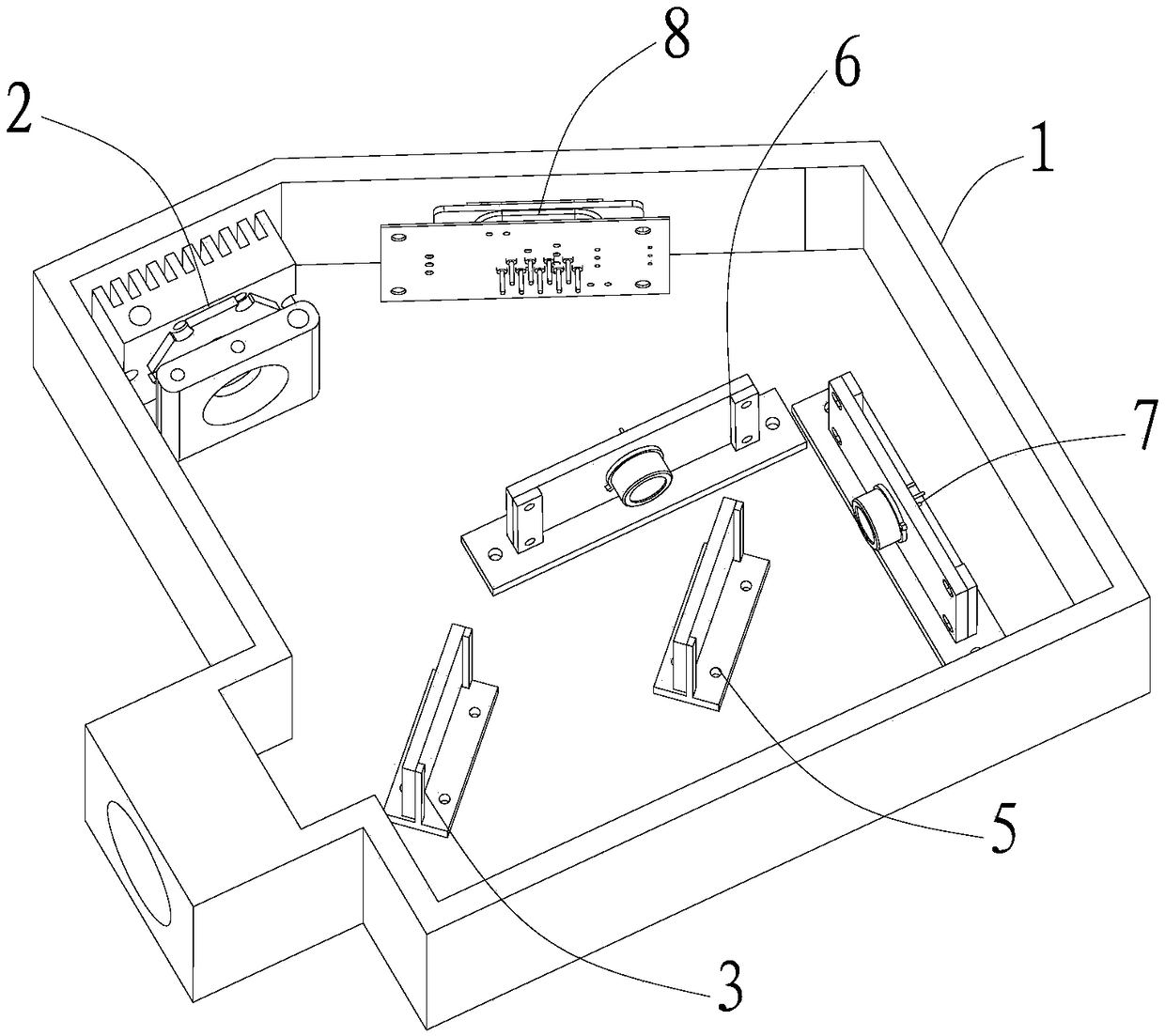
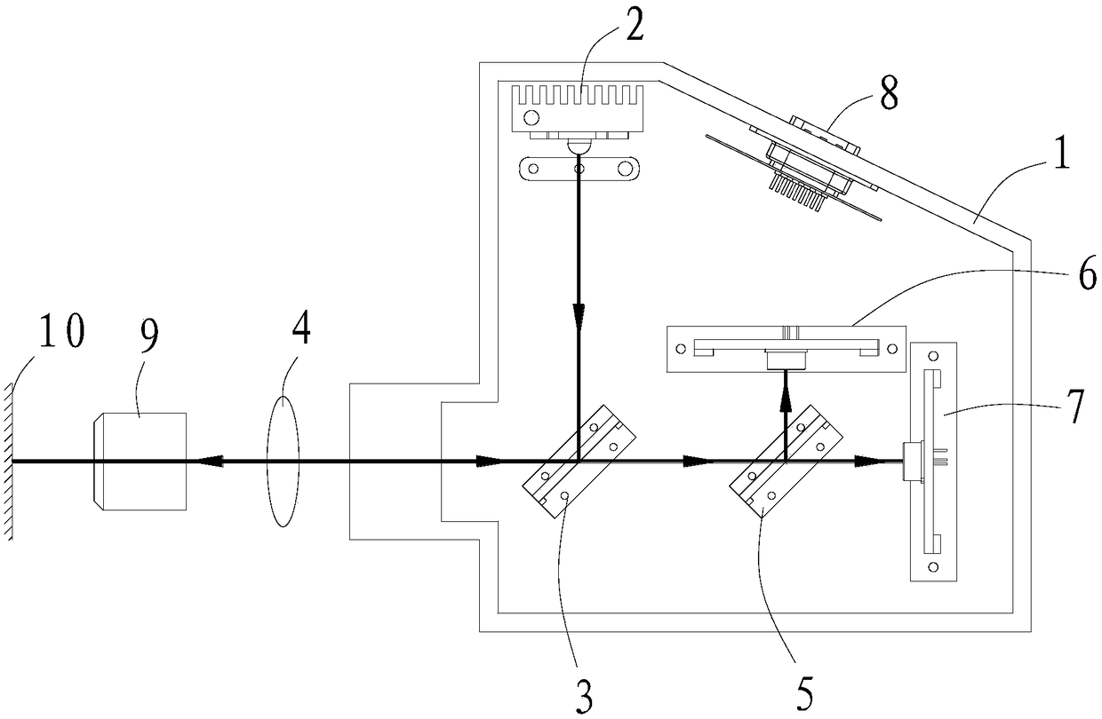
[0044] Such as figure 1 with figure 2 As shown, the autofocus device mainly includes a base 1, a transmitting module 2, a first transflective module 3, a collimating mirror 4, a second transflective module 5, a first receiving module 6, and a second receiving module 7 , the main control circuit module 8 and the objective lens 9.

[0045] The base 1 is a box structure with an accommodating cavity in the middle for accommodating installation components, and a through hole extending from the outside to communicate with the accommodating cavity.

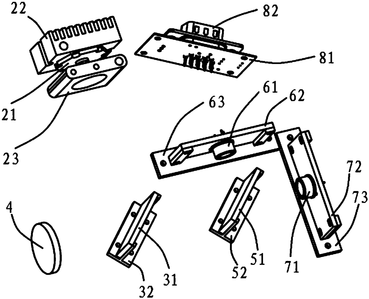
[0046] Such as image 3 As shown, the transmitting module 2 includes a light source 21, a radiator 22, and an iris 23. The light source 21 is a light source such as a light emitting diode, a laser, or a mercury lamp. The wavelength ban...

Embodiment 2

[0059] This embodiment provides an autofocus device, such as Figure 5 As shown, the autofocus device in this autofocus device adds an objective lens driving module 11 and a controller 12 on the basis of the autofocus device in the first embodiment above.

[0060] The driving module 11 is connected with the objective lens 9 and connected with the controller 12 for signals. The controller 12 is the processor of the gene sequencer, or is a separate processor, and the controller 12 is also connected to the connection terminal 82 on the base 1 for signals. The controller 12 is used to obtain the processed drive signal S and according to the drive signal S calculates the defocus amount of the sample 10, and controls the objective lens driving module 11 to drive the objective lens 9 to automatically focus according to the calculated defocus amount.

[0061] Such as Image 6 As shown, the first signal S1 (signal one), the second signal S2 (signal two) and the driving signal S (sign...

Embodiment 3

[0071] This embodiment provides an autofocus method, which is implemented based on the autofocus device in Embodiment 2.

[0072] Such as Figure 7 As shown, the autofocus method in this embodiment includes the following steps:

[0073] S001: The illuminating light is reflected into signal light;

[0074] The light source 21 emits illumination light, which is firstly reflected by the first half mirror 31 , and then irradiates the sample 10 through the collimator 4 and the objective lens 9 successively, and the sample 10 reflects the illumination light into signal light.

[0075] S002: Obtain a first signal light and a second signal light;

[0076] Obtain the first signal light reflected by the signal light through the first photodiode 61 arranged at the rear end of the reflection focus position of the second half mirror 51; The photodiode 71 acquires the second signal light into which the signal light is transmitted.

[0077] S003: Calculate the driving signal S

[0078] ...


PUM


Abstract

The invention discloses an automatic focusing method and device. The automatic focusing method comprises the following steps that illumination light emitted by a light source is reflected to pilot light in a sample; the pilot light is divided into first and second pilot light by semi-reflection semi-transmission, the reflected first pilot light is obtained behind a reflection light focusing position, and the reflected second pilot light is obtained in front of a transmitted light focusing position; a driving signal S is obtained by calculation; the defocusing quantity of the sample is calculated according to the driving signal S; and an object lens is driven to focus according to the defocusing quantity. The pilot light reflected by the sample is divided into two paths of pilot light, thetwo paths of pilot light are obtained in different positions, two signals are obtained after processing, the defocusing quantity of the sample is obtained by calculating a difference of the two signals, and the object lens is driven to implement accurate focusing after that the defocusing quantity is known. The focusing method and device simplify design of the optical path, signal calculating is simpler, the defocusing quantity can be calculated rapidly and accurately, and the object lens can be focused automatically, rapidly and accurately.

Description

technical field [0001] The invention relates to microscopic imaging technology, in particular to an automatic focusing method and device for a gene sequencer or a microscope. Background technique [0002] With the development of biotechnology, the requirements for microscopic imaging are getting higher and higher, and the target needs to be scanned and imaged. However, the depth of field of the objective lens with high magnification and large numerical aperture is very small, usually only a few microns, and the fluctuation of the sample surface has a great influence on the imaging, so a fast and high-precision real-time autofocus device is required. [0003] At present, the autofocus methods used in microscopes and gene sequencers are roughly divided into two types. One is to use image analysis methods to find the best focal plane. This method requires post-image processing. The disadvantage is that it is slow, and the cost of hardware and algorithms is high. , unable to fo...

Claims


Application Information

Patent Timeline
IPC IPC(8): G02B7/28G02B21/24
CPCG02B7/28G02B21/241
Inventor 苏泽宇克雷格·爱德华·乌里奇梁元庆郝建亮马可·弗雷德里克·森科沈梦哲黄雁樵
Owner MGI TECH CO LTD
Learn More