
Bicycle brake disc

A bicycle and disc technology, applied to bicycle accessories, bicycle brakes, brake discs, etc., can solve problems such as poor heat dissipation of hydraulic oil pipes 120, increased manufacturing and assembly costs and weight, overturning of people and vehicles, etc.

Inactive Publication Date: 2019-03-05
TIEN HSIN INDS
View PDF7 Cites 4 Cited by
  • Summary
  • Abstract
  • Description
  • Claims
  • Application Information

AI Technical Summary

Problems solved by technology

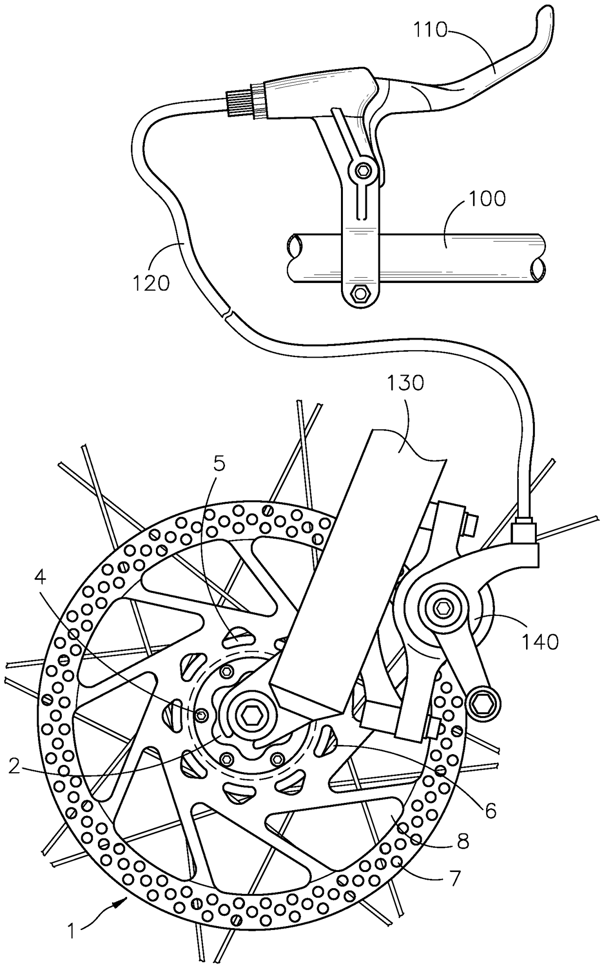
[0004] It can be seen that the brake disc 1 will generate high heat due to the clamping friction of the brake caliper 140 during braking. The known brake disc 1 does not have a cooling device to provide cooling, and the connecting hole 3 of the brake disc 1 is easily deformed due to high temperature. If it cannot be screwed firmly on the hub 5 of the bicycle, the liquid in the hydraulic oil pipe 120 may boil due to poor heat dissipation, reducing the service life of the hydraulic oil pipe 120
And if the third hole 8 on the brake disc 1 encounters a foreign object such as a finger, or a hard foreign object such as a tree branch is stuck in the middle of driving, it will cause an instant brake and stop, resulting in the danger of overturning the car.
Therefore, in order to protect the safety of users, the solution in the general industry is to add a protective cover on the outside of the brake disc 1, but adding a protective cover also increases the manufacturing and assembly cost and weight.

Method used


Image

  • Bicycle brake disc
  • Bicycle brake disc
  • Bicycle brake disc

Examples


Embodiment Construction

[0056] The present invention will be further described below in conjunction with the accompanying drawings and specific embodiments, so that those skilled in the art can better understand the present invention and implement it, but the examples given are not intended to limit the present invention.

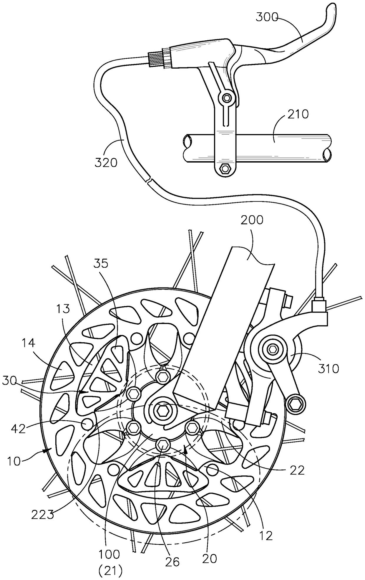
[0057] see Figure 3A , Figure 3B , the present invention discloses a bicycle brake disc, which is installed between a bicycle hub 100 and a bicycle front fork 200, and is clamped by a brake caliper 310 installed on the bicycle front fork 200 to slow down or brake the bicycle wheel. Stop, the brake caliper 310 is connected with a brake 300 on the bicycle handle 210 by a hydraulic oil pipe 320 .

[0058] see again Figure 4~Figure 7 , the present invention includes: a disc body 10, a claw piece 20, a plurality of cooling fins 30 and a plurality of first connectors 40, the disc body 10 is selected from stainless steel, cast iron, aluminum alloy, carbon fiber composite material an...


PUM


Abstract

The invention relates to a bicycle brake disc. The bicycle brake disc comprises a disc body, a claw piece, a plurality of heat dissipating fins and a plurality of first connecting pieces, wherein thedisc body is provided with an inner space, and a plurality of connecting parts extend from the inner periphery of the disc body to the inner space; the connecting parts are provided with connecting holes; the claw piece is provided with a central hole and a plurality of claw arms extending from the central hole to the outer periphery of the claw piece, wherein the claw arms are provided with through holes; the heat dissipating fins are provided with first end parts, second end parts and a plurality of assembling holes; and the first end parts and the second end parts of the heat dissipating fins are correspondingly clamped between every two adjacent connecting parts and every two adjacent claw arms, so that the connecting holes, the assembling holes and the through holes are sequentially arranged, and the first connecting pieces penetrate through the disc body, the heat dissipating fins and the the claw piece for fixing connection. According to the structure, when braking or deceleration occurs, the deformation of the disc body caused by friction and heating between a brake caliper and the disc body and the reducing of service life caused by boiling of liquid in a hydraulic oil pipe are avoided, and the danger of foreign matters getting stuck is prevented.

Description

technical field [0001] The invention relates to a brake disc of a bicycle, in particular to a brake disc of a bicycle with a cooling fin and whose thermal conductivity is greater than that of the material of the disc body, which can quickly dissipate heat and prevent foreign matter from entering to cause danger. Background technique [0002] see figure 1 , figure 2 It is a known disc brake disc for bicycles, which is generally made of steel to form a circular disc. The center of the brake disc 1 is provided with a matching hole 2 in conjunction with the hub 5 of the bicycle. The fitting hole 2 A plurality of circular connecting holes 3 are arranged in a circular arrangement on the outer periphery, and the connecting holes 3 are penetrated by a screw 4 so that the brake disc 1 is screwed to the hub 5 , and the brake disc 1 is arranged adjacent to the plurality of connecting holes 3 A plurality of first holes 6 and adjacent to the outer periphery of the brake disc 1 are als...

Claims


Application Information

Patent Timeline
IPC IPC(8): F16D65/12F16D65/847B62L1/00
CPCB62L1/005F16D65/125F16D65/128
Inventor 黄子泰
Owner TIEN HSIN INDS
Learn More