Machine cabinet member pressing and riveting moving conveying platform and pressing and riveting method
A technology of moving conveying and moving platform, applied in the direction of workbench, manufacturing tools, etc., can solve the problem of inconvenient labor intensity of workers, and achieve the effect of convenient loading and unloading work, good stability, and convenient movement.
- Summary
- Abstract
- Description
- Claims
- Application Information
AI Technical Summary
Problems solved by technology
Method used
Image

Examples
Embodiment 1
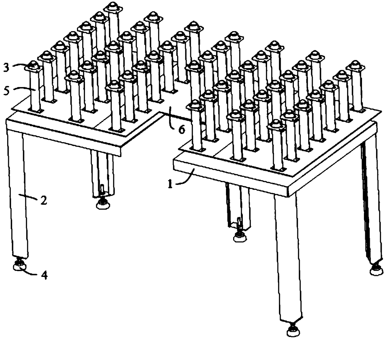
[0037] combine figure 1 , a cabinet member pressure riveting mobile conveying platform in this embodiment includes a support platform 1 and support legs 2, the support platform 1 is provided with a mobile platform 6, and the mobile platform 6 is provided with a plurality of support rods 5, The top end of the support rod 5 is provided with a rolling element 3 . In this embodiment, a guide rail is provided above the support platform 1, and a slider is provided below the mobile platform 6. The support platform 1 and the mobile platform 6 are slidably connected by the slide block and the guide rail; the mobile platform 6 is pushed to change its position on the support platform 1. The location makes it close to or away from the riveting machine, so that loading and unloading can be conveniently carried out, and the labor intensity of workers can be reduced. In order to use the pressure riveting mobile conveying platform more conveniently and effectively, the mobile platform 6 in t...
Embodiment 2
[0040] A method for pressing riveting of cabinet components in this embodiment uses the mobile riveting conveying table described in Embodiment 1 as an auxiliary riveting device, and the operation steps for performing riveting of workpieces are as follows:
[0041] Step 1. Adjust the height of the supporting leg 2 and the supporting rod 5, place the riveted part on the rolling part 3, adjust and fix the supporting leg 2 and the supporting rod 5 according to the height of the riveting machine table; and according to the height of the riveted part The shape and size of the mobile sub-platform are connected as a whole by connecting pieces;
[0042] Step 2. Push the support platform 1 to make it close to the workbench of the riveting machine; then push the mobile platform 6 to send the riveted parts into the riveting processing area;
[0043] Step 3. Push or turn the riveted piece so that the processing area is aligned with the riveting head of the riveting machine, turn on the sw...
Embodiment 3
[0047] The riveting mobile conveyor platform for cabinet components in this embodiment is basically the same as that in Embodiment 1, the difference is that: one side of the support platform 1 and the mobile platform 6 in this embodiment is provided with a U-shaped groove, which can be used during work. The workbench of the riveting machine is located in the U-shaped groove, so that both sides of the processing area of the riveted part are always on the rolling part 3, which has good stability and can avoid inaccurate positioning and occurrence of accidents caused by the shaking or deformation of the riveted part. Errors and other issues; or when working, the operator is located in the U-shaped groove, so as to facilitate the manipulation and control of the conveyor table and the workpiece.
PUM
 Abstract
Description
Claims
Application Information
 - R&D
- Intellectual Property
- Life Sciences
- Materials
- Tech Scout
- Unparalleled Data Quality
- Higher Quality Content
- 60% Fewer Hallucinations
Browse by: Latest US Patents, China's latest patents, Technical Efficacy Thesaurus, Application Domain, Technology Topic, Popular Technical Reports.
© 2025 PatSnap. All rights reserved.Legal|Privacy policy|Modern Slavery Act Transparency Statement|Sitemap|About US| Contact US: help@patsnap.com