
A rapid manufacturing equipment for electronic products

An electronic product, fast technology, applied in the direction of electrical components, electrical components, etc., can solve the problems of easy toppling, corrosion damage of components, slow cooling rate, etc., to achieve scientific and reasonable structure, avoid corrosion damage, safe and convenient to use.

Active Publication Date: 2021-02-02
锐德热力设备(东莞)有限公司
View PDF8 Cites 0 Cited by
  • Summary
  • Abstract
  • Description
  • Claims
  • Application Information

AI Technical Summary

Problems solved by technology

[0004] The present invention provides a rapid manufacturing equipment for electronic products, which can effectively solve the problem that the existing reflow soldering equipment in the above-mentioned background technology has no effective shock-absorbing equipment when it is bumped and shaken, and it is prone to dumping and long-term shaking. At the same time, the existing The reflow soldering equipment is stored in the factory for a long time. The bottom of the reflow soldering equipment is easy to breed mosquitoes and dust. Excessive dust can easily invade the inside of the equipment and cause corrosion and damage to the internal components of the reflow soldering equipment. The hidden mosquitoes are easy to bite users. Infected users who cause infectious diseases, the existing reflow soldering equipment does not have the function of preventing mosquitoes, and a large number of mosquitoes interfere with the use of reflow soldering equipment by users, because there is a heating circuit inside the reflow soldering equipment, which heats the air or nitrogen to enough After the high temperature is blown to the circuit where the components have been pasted, so the temperature of the reflow soldering equipment is high when it is used. When it needs to be cooled after use, it can only be cooled by air. This cooling method has a slow cooling rate and is easy to dissipate heat during the heat dissipation process The entry of dust and mosquitoes will cause damage to the reflow soldering equipment. The heat dissipation windows on both sides of the reflow soldering equipment can easily allow water vapor and dust to enter the interior of the equipment while ensuring heat dissipation, causing moisture and dust coverage damage to the interior of the equipment.

Method used


Image

  • A rapid manufacturing equipment for electronic products
  • A rapid manufacturing equipment for electronic products
  • A rapid manufacturing equipment for electronic products

Examples


Embodiment

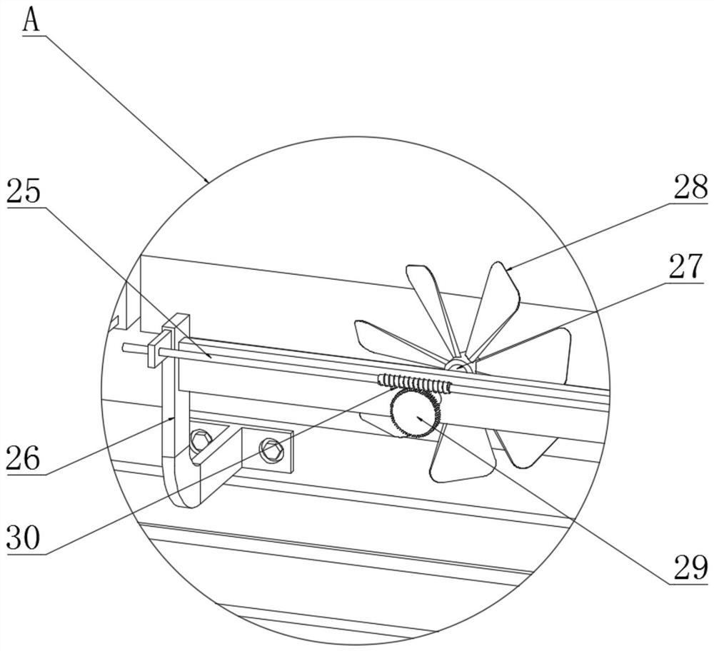
[0029] Example: such as Figure 1-5 As shown, the present invention provides a technical solution, a rapid manufacturing equipment for electronic products, including a reflow soldering box 1, a cabinet door 2 is hinged on one side of the reflow soldering box 1, and the surface of the cabinet door 2 is covered with an insect-catching sticky board 3 , the surface of the cabinet door 2 corresponds to the bottom of the insect trapping board 3, and a waste residue storage board 4 is installed. In order to prevent mosquito residues and dust from sliding down from the edge of the waste residue storage board 4, causing the ground to be dirty and difficult to clean, the waste residue storage board 4 A baffle is installed on the edge, a fixed plate 5 is symmetrically installed on the surface of the cabinet door 2 corresponding to the upper position of the sticky plate 3, and a scraper 7 is installed below the fixed plate 5 through an elastic rope 6. Vibration spring 8, damping pad 9 is ...


PUM


Abstract

The invention discloses a rapid manufacturing equipment for electronic products. A cabinet door is hinged on one side of the reflow soldering box, the surface of the cabinet door is covered with an insect-catching sticky board, and the surface of the cabinet door is installed at a position below the insect-catching sticky board. There is a waste slag storage board, and the first clamping boards are symmetrically installed on both sides of the bottom of the reflow soldering box, and a cleaning board is installed under the first clamping board. The structure of the present invention is scientific and reasonable, and it is safe and convenient to use. The sticky board lures mosquitoes, captures mosquitoes near the equipment, reduces the impact of mosquitoes on the components of reflow soldering equipment, and reduces the bite of mosquitoes on users; The water vapor and dust in the drying box are absorbed by the activated carbon in the drying box, reducing the entry of water vapor and dust into the reflow soldering equipment, preventing water vapor and dust from eroding and damaging the internal components of the reflow soldering equipment, and solving the problem of dust causing erosion and damage to the internal components of the reflow soldering equipment question.

Description

technical field [0001] The invention relates to the technical field of electronic manufacturing, in particular to a rapid manufacturing equipment for electronic products. Background technique [0002] The production process of electronic products generally requires SMT patches. After reflow soldering, the patch devices are mounted on the PCB, and then the circuit boards from SMT are manually inserted. Welding shaping is generally called secondary insertion, and then it can be tested and inspected after secondary insertion, and finally packaged for delivery. In the development process of electronic products, the need for continuous miniaturization of electronic product PCB boards has emerged. For chip components, the traditional welding method can no longer meet the needs. At first, only the reflow soldering process was used in the assembly of hybrid integrated circuit boards. Most of the components assembled and welded are chip capacitors, chip inductors, mount transistors a...

Claims


Application Information

Patent Timeline
Patent Type & Authority Patents(China)
IPC IPC(8): H05K13/04
CPCH05K13/0465
Inventor 王强
Owner 锐德热力设备(东莞)有限公司
Learn More