Condensation dehumidification device for control cabinet cooled by water cooling

A water-cooled heat dissipation and control cabinet technology, applied in substation/distribution device enclosure, substation/switchgear cooling/ventilation, substation/switch layout details, etc. Reduced dehumidification effect, etc., to achieve the effect of easy installation, good heat dissipation, and simple structure

Pending Publication Date: 2019-03-01
HANGZHOU E ENERGY ELECTRIC POWER TECH +2
View PDF3 Cites 5 Cited by
  • Summary
  • Abstract
  • Description
  • Claims
  • Application Information

AI Technical Summary

Problems solved by technology

"An intelligent outdoor terminal box dehumidification device" (application number 201610488968.2) is a dry air dehumidification device, which can realize the dehumidification inside the box, but it needs to lay a purge pipe inside, and it needs to be carried out on the existing box. modification
"Electronic dehumidifier in the terminal box" (application number: 201410121414.X) is a condensation dehumidification device, but it does not solve the problem of how to discharge the heat inside the box, and the released heat is still deposited inside the box
"Box, cabinet dehumidification circulation dryer" (application number: 201010245724.4) also has heat dissipation problems, which cannot discharge the heat inside the box in time, which affects the dehumidification effect. When the environment is humid for a long time, the dehumidification effect will continue to decrease

Method used


Image

  • Condensation dehumidification device for control cabinet cooled by water cooling
  • Condensation dehumidification device for control cabinet cooled by water cooling
  • Condensation dehumidification device for control cabinet cooled by water cooling

Examples


Embodiment Construction

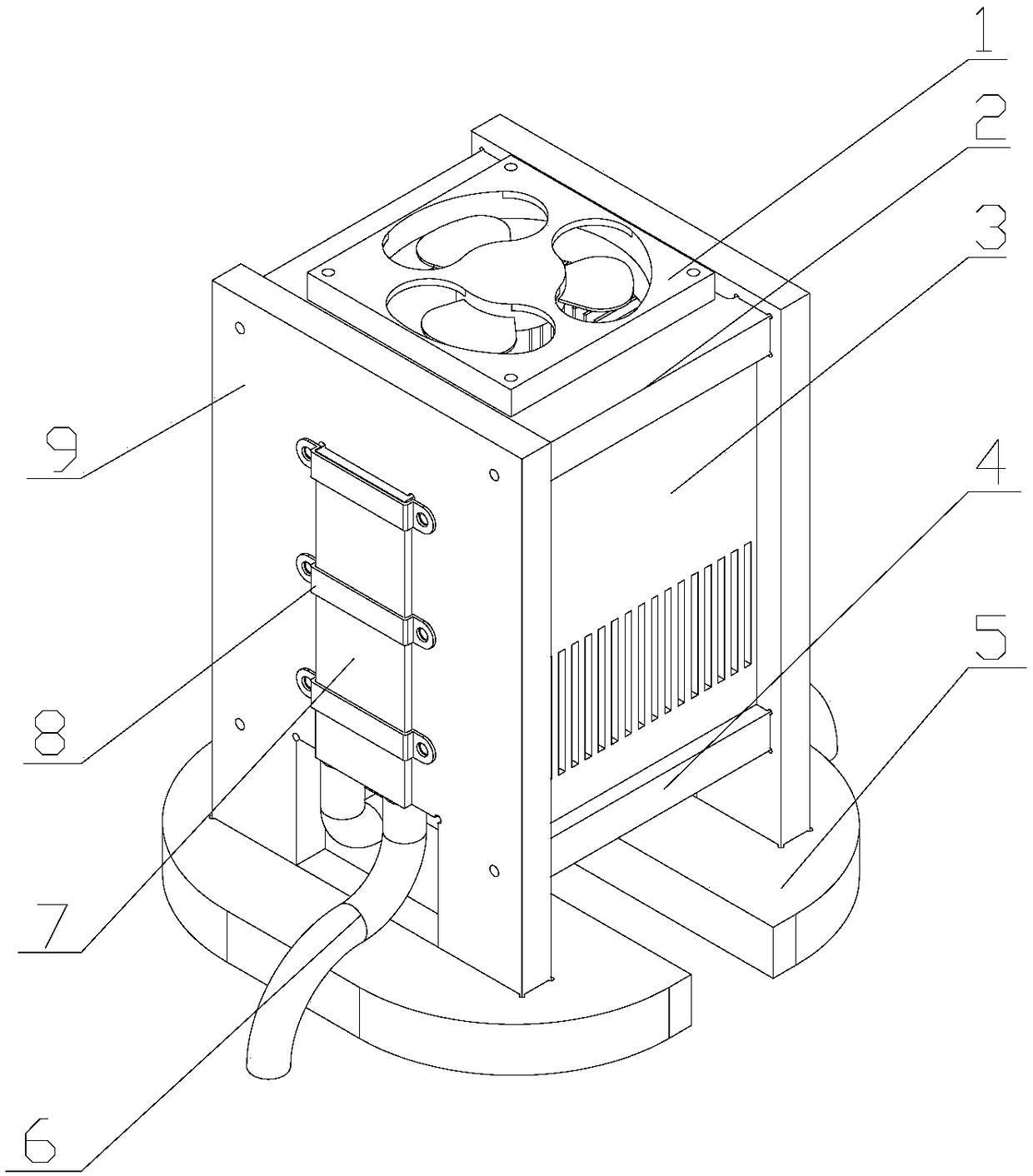
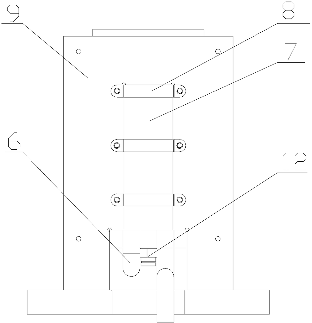
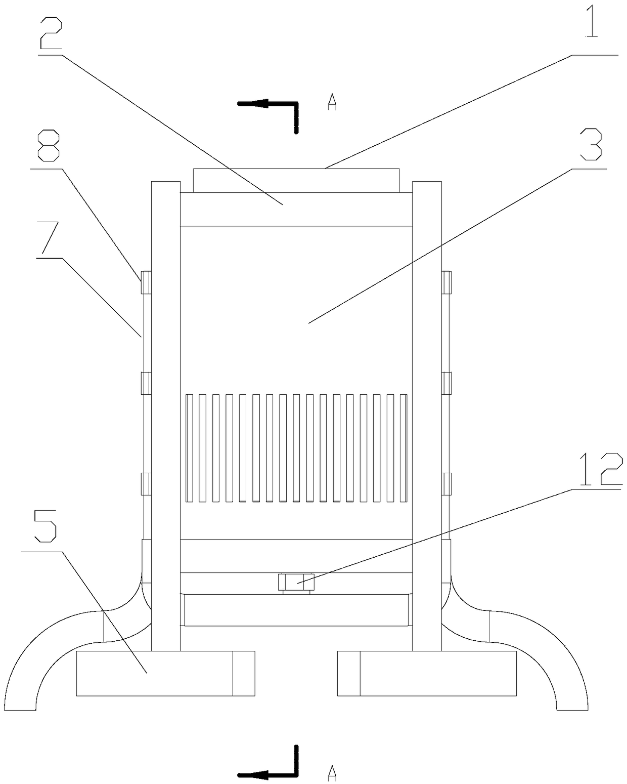
[0038] Such as Figure 1-7 As shown, the dehumidification device of the present invention is composed of a fan 1, a top connecting plate 2, a side baffle plate 3, a water collecting plate 4, a foot 5, a water pipe 6, a water cooling head 7, a fixing piece 8, a water cooling fixing plate 9, and a semiconductor refrigeration unit. Sheet 10, cooling fins 11 and pipe joints 12. The fan 1 is fixed on the top connecting plate 2 with self-tapping screws, the top connecting plate 2 and the water collecting plate 4 are connected with two water-cooling fixing plates 9 through tenon joints, and the side baffle 3 is stuck on the top connecting plate 2 and the water-cooling fixing plate 9 and in the groove of water collecting plate 4. The footing 5 is connected with the water-cooling fixing plate 9 through tenon joint. The fixing sheet 8 and the heat sink 11 clamp and fix the water cooling head 7 on the water cooling fixing plate 9 through bolts. The water pipe 6 is fixed on the water i...


PUM


Abstract

The invention discloses a condensation dehumidification device for a control cabinet cooled by water cooling. The technical scheme is that a water-cooling fixing plate is provided with a water-coolinghead, the inner side of the water-cooling head is provided with a semiconductor refrigeration sheet, and the inner side of the semiconductor refrigeration sheet is provided with a heat-dissipating sheet. A cold end of the semiconductor refrigeration sheet is attached to the heat-dissipating sheet, and a hot end is attached to the water-cooling head. The two water-cooling heads respectively on thetwo water-cooled fixing plates are connected in series, and water inlet and outlet of the water-cooling head are connected with a water pipe by a clamp, and the water pipe and a water tank form a closed loop. A fan is mounted on a top connecting plate, and a ventilation duct is arranged on a top connecting plate below the fan and is used for blowing air in the control cabinet to a tank. A water collecting plate is provided with a pipe joint fixing hole, and a pipe joint is fixed in the pipe joint fixing hole. The device can realize condensation and dehumidification of the air in the control cabinet, and can discharge heat generated by the hot end of the semiconductor refrigeration sheet to the control cabinet to prevent a condensation effect from being reduced caused by poor heat dissipation of the hot end.

Description

technical field [0001] The invention relates to a condensation and dehumidification device in a control cabinet, in particular to a condensation and dehumidification device for a control cabinet through water cooling and heat dissipation. Background technique [0002] At present, some outdoor sealed boxes of power grid substations are affected by geographical environmental factors such as coastal areas, rainy, and humid, and there are moisture problems inside the boxes, which are prone to grid equipment accidents. If the isolation and grounding switch box is damp, there may be problems such as the switch knife jamming and refusal to move or the switch knife malfunctioning; if the circuit breaker mechanism box is damp, there may be problems such as circuit breaker switch malfunction and abnormal sending of letters; such as GIS equipment or transformer HSBC If the cabinet is damp, it may cause the smart terminal to crash and stop working, and the device may be abnormal. [00...

Claims


Application Information

Patent Timeline
Patent Type & Authority Applications(China)
IPC IPC(8): H02B1/56H02B1/28
CPCH02B1/28H02B1/565
Inventor 孙庆峰汤义勤王炯耿张杰周正强梅简罗宏建魏燕定邹宏亮吴坚花国祥陈胤桢徐胜
Owner HANGZHOU E ENERGY ELECTRIC POWER TECH
Why Eureka
Try Eureka