System for detecting number of fallen particles during working process of valve

A working process and particle counter technology, which is applied in the direction of measuring devices, mechanical valve testing, individual particle analysis, etc., can solve problems such as the quality impact of semiconductors or photovoltaic modules, and achieve the effect of easy operation and simple detection principle

Active Publication Date: 2019-03-01
九川真空科技成都有限公司 +1
View PDF6 Cites 0 Cited by
  • Summary
  • Abstract
  • Description
  • Claims
  • Application Information

AI Technical Summary

Problems solved by technology

[0003] The purpose of the present invention is to provide a system for detecting the amount of particles falling off during the working process of the valve, through which the number of particles falling off during the working process of the valve can be detected, so that the manufacturer and purchaser of the valve can accurately understand the amount of particles falling off the valve data, which solves the problem that the quality of semiconductors or photovoltaic modules is affected due to the particle shedding of the valve not meeting the requirements

Method used


Image

  • System for detecting number of fallen particles during working process of valve
  • System for detecting number of fallen particles during working process of valve
  • System for detecting number of fallen particles during working process of valve

Examples


Embodiment 1

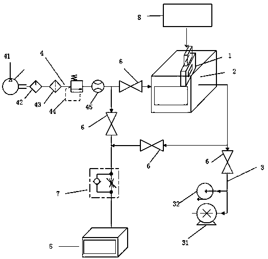
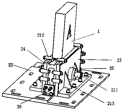
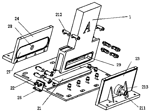
[0059] This embodiment provides a system for detecting the number of particles falling off during valve operation, which includes a vacuum device, a valve to be tested 1, a valve drive device to be tested 8, a gas inlet device 4 and a particle counter 5, and the vacuum device includes The cavity 2 and the vacuuming device 3, the cavity 2 is connected with three pipelines, one of which is a gas inlet pipeline, one of which is an outlet pipeline, and the last one is a vacuuming pipeline, which is connected to the vacuuming device 3. The gas inlet pipeline is connected to the gas inlet device 4, the outlet pipeline is connected to the particle counter 5, the gas inlet device 4 is connected to the particle counter 5 through a branch pipeline, and the valve driving device 8 to be tested is connected to the valve 1 to be tested. The valve driving device 8 drives the valve 1 to be tested to open and close. The valve 1 to be tested is placed in the cavity 2. Valves are installed on the...

Embodiment 2

[0074] The method for detecting the number of particles falling off during the working process of the valve provided in this embodiment is specifically (for the convenience of illustration, combined with figure 1 Be explained):

[0075] Step 1: Connect the gas inlet device 4, the vacuum device 3 and the particle counter 5 on the cavity 2, insert the valve 1 to be tested into the cavity 2, connect the valve 1 to be tested to the valve driving device 8, and drive the valve driving device 8 The valve 1 to be tested is opened and closed; the valve I6 is installed on the connecting pipeline between the gas inlet device 4 and the cavity, the valve II61 is installed on the pipeline connecting the gas inlet device 4 and the particle counter 5, and the valve II61 is installed on the pipeline connecting the gas inlet device 4 and the cavity. Install valve Ⅲ62 on the pipeline connected to 2, and install valve Ⅳ63 on the pipeline connected to the vacuum device 3 and the cavity; firstly cl...

Embodiment 3

[0080] This embodiment is basically the same as Embodiment 2, except that the gas is introduced into the cavity 2 through the gas inlet device 4 first, and then the gas enters the cavity 2 and then enters the particle counter 5 for counting, and records the value displayed by the particle counter. Number a1, and then clear the particle counter, pass the gas with the same flow rate into the particle counter that has been cleared through the gas inlet device for counting, record the number b1 displayed by the particle counter, and calculate the number of particles falling off c1=a1 -b1.


PUM


Abstract

The invention discloses a system for detecting the number of fallen particles during the working process of a valve, comprising a vacuum device, a to-be-detected valve, a to-be-detected valve drivingdevice, a gas injecting device and a particle counter, wherein the vacuum device comprises a cavity and a vacuuming device; the to-be-detected valve driving device is connected to the to-be-detected valve; the to-be-detected valve is placed in the cavity; and the vacuum device is connected to the gas injecting device and the particle counter. The system can detect the number of fallen particles during the working process of the valve, so that a manufacturer and a purchaser of the valve can accurately understand the number of the fallen particles of the valve, thereby solving the problem that the quality of a semiconductor or photovoltaic module is affected because the number of the fallen particles of the valve does not meet a requirement.

Description

technical field [0001] The invention relates to a detection system for a valve, in particular to a system for detecting the number of particles falling off during the working process of the valve. Background technique [0002] Vacuum valves are used in the manufacturing of semiconductors and photovoltaic modules. Due to the very high requirements for vacuum valves in the manufacturing process of semiconductors and photovoltaic modules, in addition to some conventional requirements (such as size, sealing, impact resistance, etc.), there are also certain requirements for the amount of particles shed by vacuum valves during work. , if the amount of particle shedding is large, it will affect the quality of the entire semiconductor and photovoltaic modules. Therefore, it is necessary to detect the particle shedding amount of the vacuum valve, but there is no prior art for detecting the particle shedding amount of the vacuum valve at present. Due to the lack of relevant detectio...

Claims


Application Information

Patent Timeline
Patent Type & Authority Applications(China)
IPC IPC(8): G01M13/003G01N15/10
CPCG01M13/00G01N15/10G01N2015/1062
Inventor 张智明孙围华靳毅刘绘生余健宋敏陈泽芸王丛岭蒋丹
Owner 九川真空科技成都有限公司
Why Eureka
Try Eureka