Anti-fall stable safety door

A safety door, stable technology, applied in the field of safety doors, can solve the problems of easy to be pryed or knocked open, low safety performance, shorten the service life of the safety door, etc., to achieve the effect of improving safety and improving service life

Inactive Publication Date: 2019-03-01
苏州德特尼罗电子科技有限公司
View PDF0 Cites 0 Cited by
  • Summary
  • Abstract
  • Description
  • Claims
  • Application Information

AI Technical Summary

Problems solved by technology

[0004] The existing anti-theft door only relies on the lock body to engage the door body and the door frame, which is easy to be pried open or knocked open under the action of external force, and the safety performance is low; at the same time, during the long-term use of the anti-theft door, the door body and the door frame Constant impact reduces the service life of the security door

Method used


Image

  • Anti-fall stable safety door
  • Anti-fall stable safety door
  • Anti-fall stable safety door

Examples


Embodiment 1

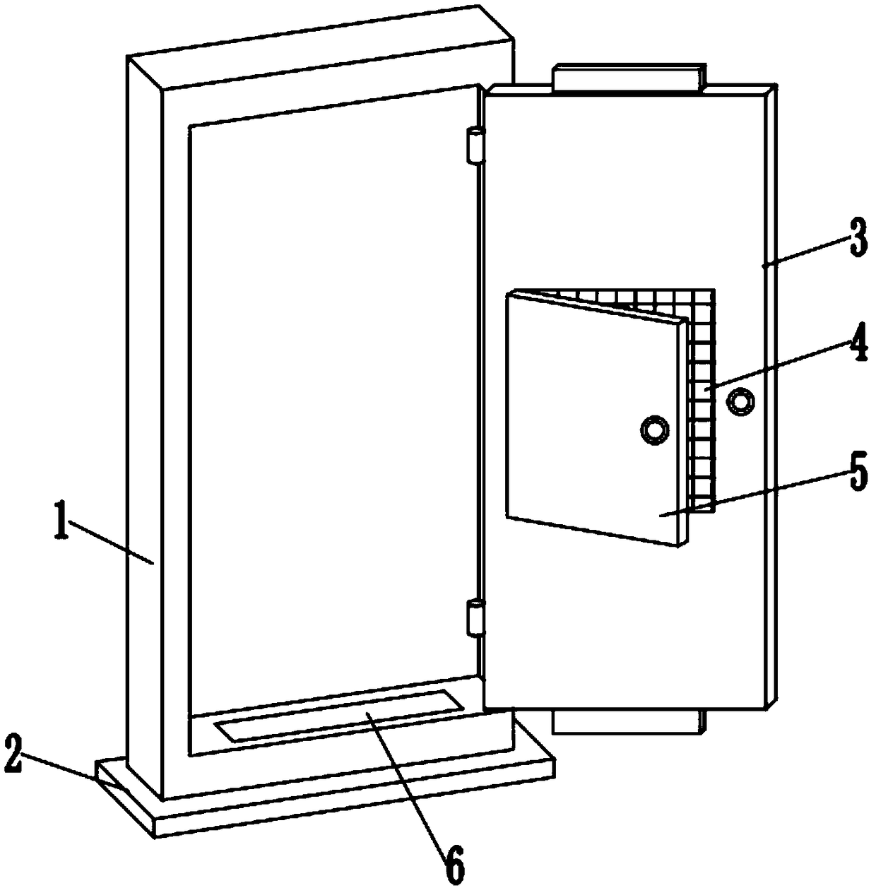
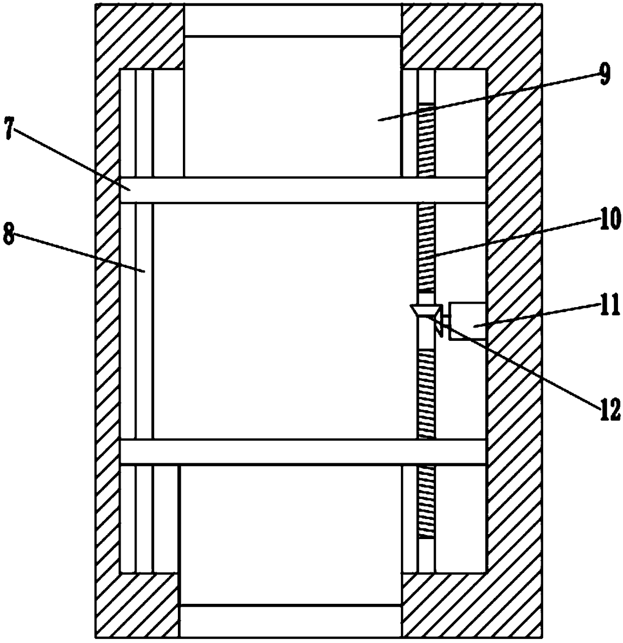
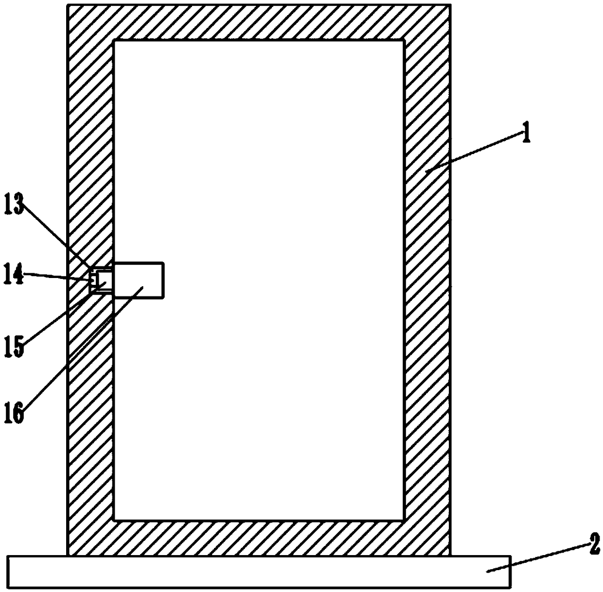
[0024] see Figure 1~3 , in the embodiment of the present invention, a safety door with anti-fall stability includes a door frame 1, a base 2 and a door body 3; It is steel and wood, and the left and right sides inside the door body 3 are symmetrically provided with slide rods 8 and screw rods 10. The slide rods 8 are fixedly installed inside the door body 3, and the screw rods 10 are rotatably installed inside the door body 3. The upper and lower sides of the door body 3 Both sides are also symmetrically provided with two lifting plates 7, the left side of the lifting plate 7 is slidably connected with the slide bar 8, the right side of the lifting plate 7 is screwed with the screw rod 10, and the outside of the lifting plate 7 is fixedly equipped with a block 9, The clamping block 9 is slidingly connected with the door body 3; the upper and lower sides of the door frame 1 are symmetrically provided with a first clamping groove 6 that cooperates with the clamping block 9. Whe...

Embodiment 2

[0027] see Figure 1~6 , in the embodiment of the present invention, a safety door with anti-fall stability includes a door frame 1, a base 2 and a door body 3; It is steel and wood, and the left and right sides inside the door body 3 are symmetrically provided with slide rods 8 and screw rods 10. The slide rods 8 are fixedly installed inside the door body 3, and the screw rods 10 are rotatably installed inside the door body 3. The upper and lower sides of the door body 3 Both sides are also symmetrically provided with two lifting plates 7, the left side of the lifting plate 7 is slidably connected with the slide bar 8, the right side of the lifting plate 7 is screwed with the screw rod 10, and the outside of the lifting plate 7 is fixedly equipped with a block 9, The clamping block 9 is slidingly connected with the door body 3; the upper and lower sides of the door frame 1 are symmetrically provided with a first clamping groove 6 that cooperates with the clamping block 9. Whe...


PUM


Abstract

The invention discloses an anti-fall stable safety door. The anti-fall stable safety door comprises a door frame, a base and a door body. The door body is rotatably installed in the door frame, a slide bar and a screw rod are symmetrically arranged on the left and right sides of the inner part of the door body, two lifting plates are symmetrically arranged on the upper and lower sides of the doorbody, the left sides of the lifting plates are in sliding connection with the slide bar, the right sides of the lifting plates are in threaded connection with the screw rod, clamping blocks are fixedly arranged on the outer sides of the lifting plates, and the clamping blocks are in sliding connection with the door body. First clamping grooves which are matched with the clamping blocks are symmetrically formed in the upper and lower sides of the door frame. A lock body is arranged at a handle of the door body, a second clamping groove matched with the lock body is formed in the door frame, anda button is fixedly arranged in the second clamping groove. The anti-fall stable safety door improves the overall safety of the door body. A limiting block and a limiting groove are further formed toprotect the door frame, the base and the door body, and prolong the service life of the safety door.

Description

technical field [0001] The invention relates to a safety door, in particular to a fall-resistant and stable safety door. Background technique [0002] The anti-theft door is equipped with an anti-theft lock, which can resist abnormal opening under certain conditions within a certain period of time. It has certain safety protection performance and meets the corresponding anti-theft safety level. [0003] The full name of anti-theft door is "anti-theft safety door". It has both anti-theft and safety performance. According to the "General Technical Conditions for Anti-theft Safety Doors", a qualified anti-theft door cannot be pried open by ordinary hand tools such as chisels, screwdrivers, crowbars, and portable electric tools such as electric hand drills within 15 minutes or a 615 square millimeter hole can be opened on the door leaf. opening, or a 38 mm2 opening within a semicircle of 150 mm2 at the locking point. And the lock used on the security door must be the special ...

Claims


Application Information

Patent Timeline
Patent Type & Authority Applications(China)
IPC IPC(8): E06B5/11E06B3/36E06B3/70E06B1/52E06B7/30E06B9/52E05B65/06E05F5/02
CPCE06B5/113E05B65/06E05F5/02E05Y2900/132E06B1/52E06B3/36E06B3/70E06B7/30E06B9/52E06B2003/7049
Inventor 吴继达
Owner 苏州德特尼罗电子科技有限公司
Why Eureka
Try Eureka