High-assembling-rate steel tube concrete frame structure system and connecting method

A technology of steel pipe concrete and frame structure, which is applied to truss structures, building structures, joists, etc., and can solve the problems of heavy installation work and low assembly efficiency, so as to prevent potential safety hazards, improve efficiency, and increase the docking area Effect

Active Publication Date: 2019-03-01
CHINA MCC17 GRP
View PDF5 Cites 5 Cited by
  • Summary
  • Abstract
  • Description
  • Claims
  • Application Information

AI Technical Summary

Problems solved by technology

[0006] The technical problem to be solved by the present invention is the technical problem of large installation workload and low assembly efficiency, so a high assembly rate concrete filled steel tube frame structure system and connection method are proposed

Method used


Image

  • High-assembling-rate steel tube concrete frame structure system and connecting method
  • High-assembling-rate steel tube concrete frame structure system and connecting method
  • High-assembling-rate steel tube concrete frame structure system and connecting method

Examples


Embodiment 1

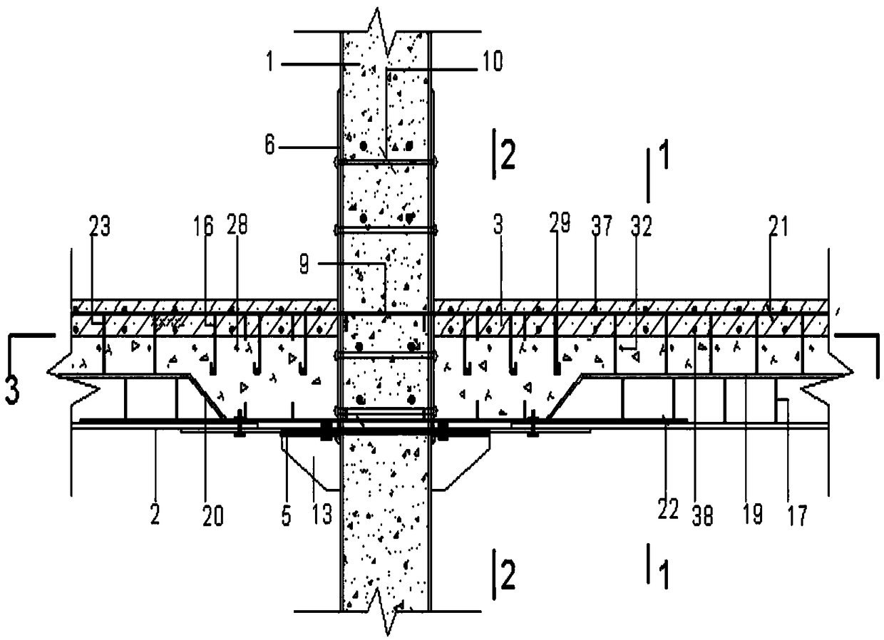
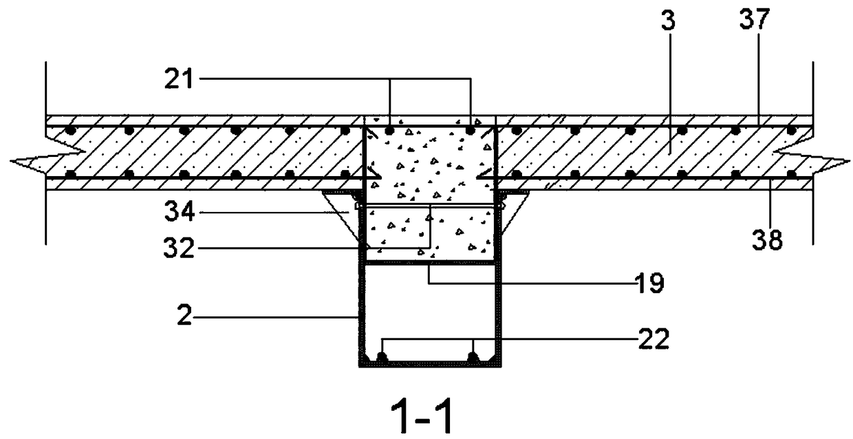
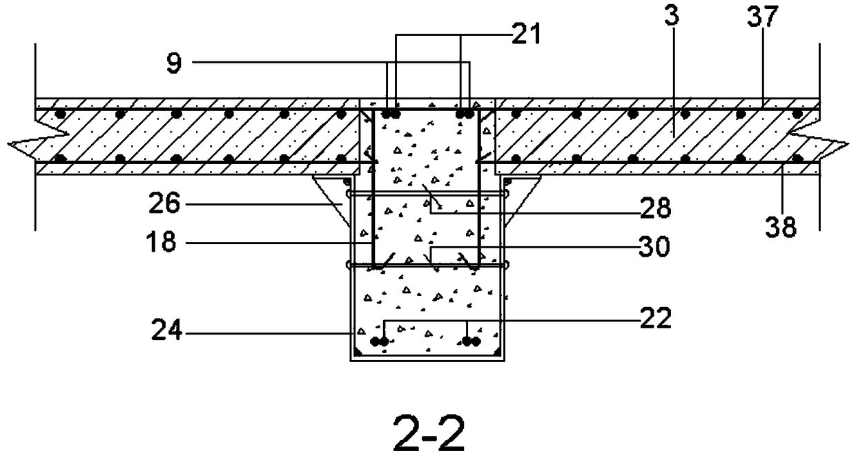
[0055] A high-assembly-rate concrete-filled steel tube frame structure system according to the present invention includes concrete columns 1 composed of steel pipes and concrete, composite beams 2 composed of semi-open steel boxes and concrete, concrete slabs 3, and column-to-column flange connection nodes , beam-column joints, post-cast concrete on site, where:

[0056] The lower part of the side wall of the concrete column 1 is penetrated with a reinforced steel sleeve 6, and the wall thickness of the reinforced steel sleeve 6 is greater than that of the concrete column 1 and protrudes 300-500mm from the floor; the lower part of the side wall of the concrete column 1 and the side of the reinforced steel sleeve 6 The walls are provided with a through hole 7 and a through hole 8; the through hole 7 and the through hole 8 are respectively penetrated with an anchor bar 9 in the column and a first tie anchor bolt 10; the concrete column 1 and the reinforced steel sleeve 6 first pa...

Embodiment 2

[0062] A connection method for a high assembly rate concrete-filled steel tube frame structure system, the specific steps are as follows:

[0063] Step 1. Fix the reinforced steel sleeve 6

[0064] The reinforced steel sleeve 6 is penetrated through the lower part of the concrete column 1, the bottom of the reinforced steel sleeve 6 is 10-20mm higher than the bottom of the concrete column 1, and the through hole 7 and the through hole 8 are opened, and the anchor bar (9) and the second A tie anchor bolt 10 runs through the through hole 7 and the through hole 8 respectively, and the two ends of the anchor bar 9 in the column are folded into a 90° hook with a special tool, and the required concrete column 1 is subjected to this treatment in turn, Leave a concrete column 1 not pierced with anchor bar 9 in the column for subsequent use;

[0065] Step 2. Connect the flange

[0066] The upper flange 4 and the lower flange 5 are respectively welded to the upper and lower ends of th...


PUM


Abstract

The invention discloses a high-assembling-rate steel tube concrete frame structure system and a connecting method, and belongs to the field of fabricated building structures. The high-assembling-ratesteel tube concrete frame structure system comprises a concrete column, a combined beam, a concrete plate, a column-column flange connecting joint, a beam-column connecting joint, a field post-cast concrete and a mounting method thereof. Concrete upper and lower columns are connected together through a column top flange and a column bottom flange by bolts, the column bottom flange is connected with a U-shaped steel plate by bolts, the inside of the U-shaped steel plate is connected with the combined bema by bolts, the concrete plate is mounted at the outwards turned flange of the combined beamand the outwards turned flange of the U-shaped steel plate, and is fixed by anchoring pulling anchor bolts, and finally, the field post-cast concrete is poured finally. The invention mainly solves the problem that an existing concrete frame structure is high in assembling operation amount and low in mounting efficiency.

Description

technical field [0001] The invention belongs to the field of prefabricated building structures, and in particular relates to a steel pipe concrete frame structure system with a high assembly rate and a connection method. Background technique [0002] Compared with the reinforced concrete structure system and light steel structure system widely used in residential industrialization at the present stage, the steel tube concrete composite structure system has the advantages of fast construction speed of steel structure, high rigidity of concrete structure, low cost, and high bearing capacity. Good shape and toughness, convenient production and construction, good fire resistance, etc., have good working performance and economic benefits. [0003] In the existing concrete-filled steel tube frame structure, the concrete inside the steel tube is generally cast-in-place, and the pouring workload is heavy, the vibration is inconvenient, and it is difficult to detect and control the p...

Claims


Application Information

Patent Timeline
Patent Type & Authority Applications(China)
IPC IPC(8): E04C3/34E04C3/20E04B1/58
CPCE04B1/5831E04C3/20E04C3/34
Inventor 吴二军邵辉学付金笛蒋勇金仁才正清柳荣芳
Owner CHINA MCC17 GRP
Why Eureka
Try Eureka