
Aerial vehicle structure

A technology of vehicle and skeleton structure, which is applied in the direction of superstructure sub-assembly, connection between superstructure sub-assemblies, building components, etc. or voids, etc., to facilitate handling and assembly, improve strength and stability, and maintain structural integrity

Inactive Publication Date: 2019-03-01
张跃
View PDF7 Cites 7 Cited by
  • Summary
  • Abstract
  • Description
  • Claims
  • Application Information

AI Technical Summary

Problems solved by technology

[0002] .Most of the existing air vehicle shells are made of titanium alloy, aluminum-lithium alloy and other materials through stamping and forming to form various structures of the vehicle. The aircraft made of these materials mainly have the following defects: First, most of them are solid The structure is heavy; second, once damaged, it is not easy to repair; third, the performance of vibration isolation and noise reduction is poor; fourth, the thermal insulation effect is poor
However, the honeycomb core is connected into one body through multiple honeycomb structures, and the upper and lower ends of the honeycomb core are in line contact with the upper and lower panels. During the welding process, the welding process between the honeycomb core and the upper and lower panels will be weak, and gaps or voids will easily occur. , resulting in unstable overall structure, low strength, poor impact resistance, etc.
In addition, the honeycomb core can only be connected into one body. As long as one part of the connection is not firm, it will easily affect other parts over time, thereby reducing the stability of the overall structure, thereby reducing the strength and service life.

Method used


Image

  • Aerial vehicle structure
  • Aerial vehicle structure
  • Aerial vehicle structure

Examples


Embodiment 1

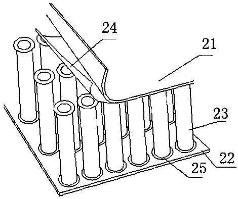
[0052] Such as figure 1 Shown: a kind of aircraft, its fuselage 1 comprises fuselage, wing and empennage, and wherein fuselage comprises fuselage skin 11 and is located at the first bulkhead 12 of fuselage skin 11 inner cavity, girder 13. The wing includes a wing skin 14 and a longitudinal wall 15 located in the inner cavity of the wing skin. The bottom of the aircraft includes a floor 16, a fuselage skin 11, a second partition frame 17 and a beam 18 arranged in the inner cavity of the fuselage skin.

[0053] Wherein, the fuselage skin 11, the wing skin 14, the longitudinal wall 15, and the floor 16 are all made of metal plates. Wherein, the fuselage skin 11 and the wing skin 14 are made of arc-shaped metal plates. The vertical walls 15 and the floor 16 are made of sheet metal of planar construction.

[0054] Adjacent metal plates and between metal plates and other parts of the body can be connected by means of welding, screwing or the like.

[0055] Such as figure 2 or ...

Embodiment 2

[0063] On the basis of Embodiment 1, the first bulkhead 222, the girder 223, the second bulkhead 227 and the cross beam 228 are also made of metal plates. Wherein the first frame 222 and the second frame 227 are welded by a plurality of arc-shaped metal plates, and the truss 223 and the cross beam 228 are both made of plane metal plates. The second bulkhead 227 and the beam 228 are welded into one body and reinforced by bolts.

[0064] The skeleton structure of this embodiment is made of metal plates, which not only ensures the strength but also improves the light weight.

Embodiment 3

[0066] On the basis of Embodiment 1, the seats in the aircraft are also made of sheet metal.

[0067] The backrest of the seat is a metal plate with a curved structure, while the seat is a metal plate with a planar structure.


PUM


Abstract

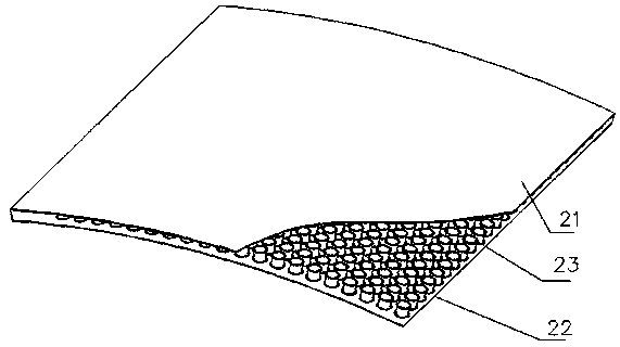
An air vehicle structure comprises a framework structure and a skin connected with the framework structure, wherein at least one of the framework structure and the skin is made of plate metal; the plate metal comprises a first panel, a second panel as well as a plurality of hollow tubes arranged between the first panel and the second panel, and brazing layers are arranged between the hollow tubesand the first panel as well as between the hollow tubes and the second panel; a turning edge is arranged at at least one end of the hollow tubes. The aerial vehicle structure has the advantages of being small in self-weight, high in strength, stable in structure, high in impact resistance, capable of insulating sound and reducing noise, resistant to high temperature, corrosion and vibration, longin service life, capable of being carried and spliced and the like.

Description

technical field [0001] The invention relates to the field of vehicles, in particular to an air vehicle structure. Background technique [0002] .Most of the existing air vehicle shells are made of titanium alloy, aluminum-lithium alloy and other materials through stamping and forming to form various structures of the vehicle. The aircraft made of these materials mainly have the following defects: First, most of them are solid The structure is heavy; second, once damaged, it is not easy to repair; third, the performance of vibration isolation and noise reduction is poor; fourth, the insulation effect is poor. [0003] At present, there are also shell structures made of honeycomb panels. The honeycomb panels include upper and lower panels and honeycomb cores, thereby improving lightweight. However, the honeycomb core is connected into one body through multiple honeycomb structures, and the upper and lower ends of the honeycomb core are in line contact with the upper and lower...

Claims


Application Information

Patent Timeline
Patent Type & Authority Applications(China)
IPC IPC(8): B64C1/12
CPCA45C5/02A45C5/045A45C5/14A45C13/001A45C13/04A45C13/36A47B13/08A47B96/02A47B96/206A47B2220/008A47C7/00B32B1/00B32B3/08B32B3/085B32B3/12B32B3/20B32B3/266B32B7/08B32B15/01B32B15/011B32B15/012B32B15/013B32B15/015B32B15/017B32B15/18B32B15/20B32B2250/40B32B2307/102B32B2307/304B32B2307/306B32B2307/3065B32B2307/50B32B2307/558B32B2307/714B32B2307/718B32B2419/00B32B2439/00B32B2479/00B32B2605/08B32B2605/10B32B2605/12B32B2605/18B62D25/00B62D27/02B62D29/00B63B3/26B63B3/48B63B3/56B64C1/12B64C2001/0081B65D81/3818B65D90/028E01B1/002E01B2204/09E01D19/02E01D19/083E01D19/125E01D2101/30E06B3/7015E06B2003/7049E21D9/14E21D11/155E21D11/18F16L9/21F16L59/02
Inventor 张跃
Owner 张跃
Learn More