
A designing and implementation method of an elastic element module

A technology of elastic components and implementation methods, applied in computing, special data processing applications, instruments, etc., to achieve the effect of improving design efficiency, speed and efficiency, and eliminating duplication of labor

Inactive Publication Date: 2019-02-26
成都数模码科技有限公司
View PDF5 Cites 5 Cited by
  • Summary
  • Abstract
  • Description
  • Claims
  • Application Information

AI Technical Summary

Problems solved by technology

At present, the most advanced mold design technology only makes some scattered parametric models for some knowledge points. For the randomness of the input and the complexity of the environment (compared to a certain part) brought about by it, There is no application of mathematical models to solve the problem; the final result can only be obtained through manual judgment and manual cycle trial and error

Method used


Image

  • A designing and implementation method of an elastic element module

Examples


Embodiment Construction

[0030] The method of the present invention will be further described in detail below in conjunction with the drawings and the embodiments of the present invention.

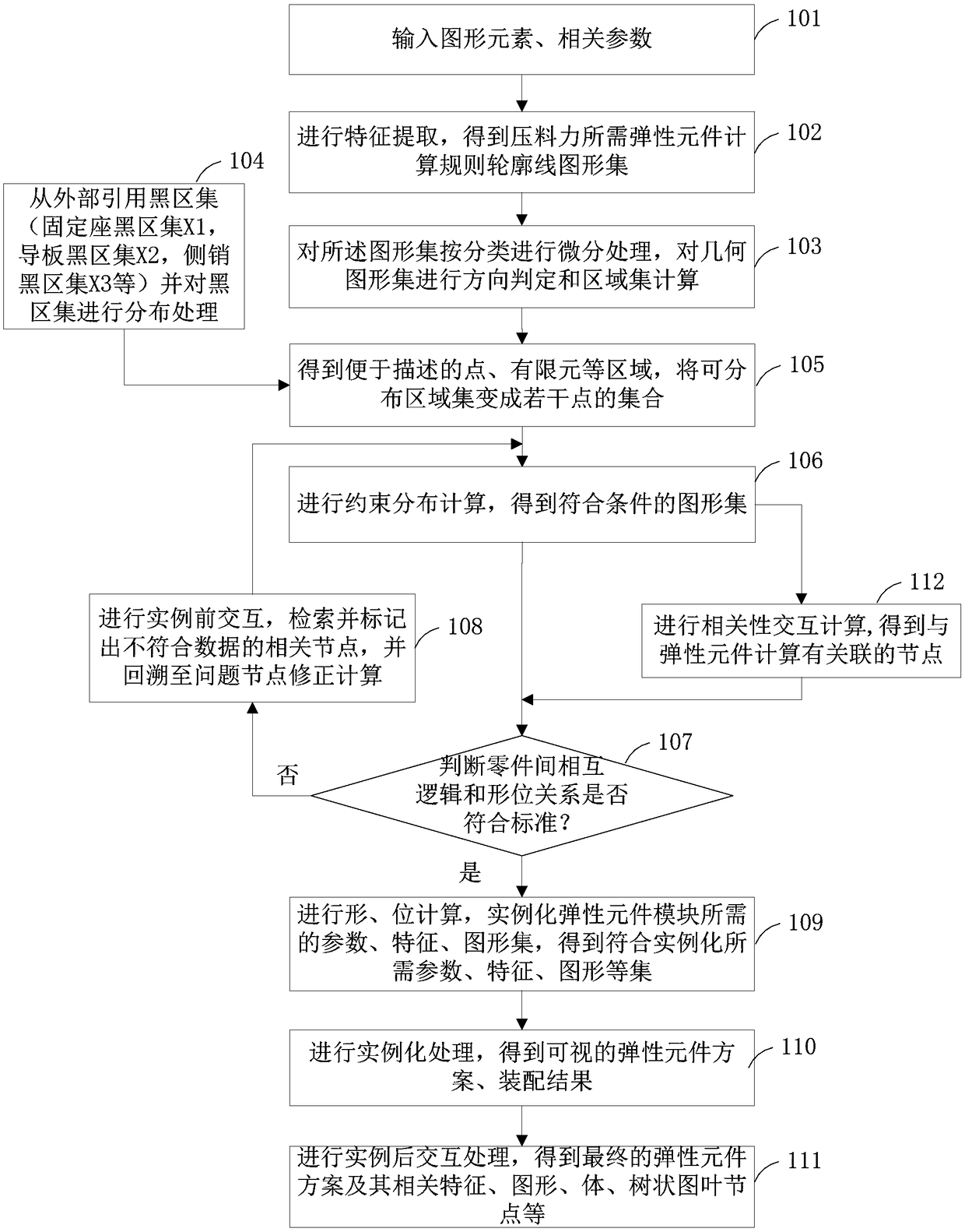
[0031] figure 1 It is a schematic flow diagram of the design and realization method of the elastic element module of the embodiment.

[0032] Such as figure 1 As shown, the design and realization method of the elastic element module mainly includes the following steps:

[0033] Step 101: Input graphic elements and related parameters. The input graphic elements and related parameters include the upper presser segmentation curve (CSUP), work profile (SW), punching set (PS), shaping set (BS), flanging set (DFS), stroke ( ST) and part material thickness (PT), etc.

[0034] Step 102: Perform feature extraction to obtain the elastic element required for the pressing force (F) to calculate a set of regular contour lines.

[0035] Here, the feature extraction process is specifically: extracting the original graphics according t...


PUM


Abstract

The invention discloses a designing and implementation method of an elastic element module, which comprises the following steps: A, inputting graphic elements and related parameters; B, carrying out feature extraction to obtain a regular contour graph set for calculating elastic element required by pressing force; C, carrying out differential processing, and carrying out direction determination and area set calculation on that geometric graph set; D, quoting that black area set from the outside, and distributing the black area set; E, obtaining a region of a point and a finite element which are convenient to be described, and converting that distributable region set into a set of several points; F, obtaining a graphics set according with that conditions; G, judging whether that mutual logic and the shape-position relationship among the part conform to the standard; H, carrying out shape and position calculation to obtain a set of parameters, characteristic and graphics required by thatinstantiation; I, carrying out instantiation processing to obtain a visualized elastic element scheme and an assembly result; J, carrying out the post-example the interactive processing, and obtaining the final elastic element plan and its related characteristic, the graph, the volume, the tree diagram leaf node.

Description

Technical field [0001] The invention relates to intelligent mold design and manufacturing technology, in particular to a design and realization method of an elastic element module. Background technique [0002] In the existing mold design technology, it is generally necessary to manually pass the DL diagram to parameterize the elastic element, calculate the required force of the mold, determine the required elastic element model, select the model in the elastic element standard part library, and import it into the mold manually Figure, and then move to a suitable position, these operations need to be determined by the designer's manual subjective calculation to move. There are problems of high repetitiveness and low efficiency. In the existing scheme, there is no technology to automatically identify the design elements of the elastic element, automatically calculate the shape and size, automatically select the model, and automatically interact with the relationship between the p...

Claims


Application Information

Patent Timeline
Patent Type & Authority Applications(China)
IPC IPC(8): G06F17/50
CPCG06F30/17
Inventor 宋和立李恒许号全张福其他发明人请求不公开姓名
Owner 成都数模码科技有限公司
Learn More