Ultrasonic range finding obstacle avoidance system

An ultrasonic wave and obstacle avoidance technology, which is applied in radio wave measurement systems, sound wave reradiation, and measurement devices, can solve problems such as increasing the difficulty of filter processing circuits, echo signal fluctuations, and response rate reduction, and achieve the minimum improvement The effects of detecting blind areas, increasing emission intensity, and improving efficiency

Pending Publication Date: 2019-02-26
CHENGDU EVENTEC SCI & TECH CO LTD
View PDF0 Cites 3 Cited by
  • Summary
  • Abstract
  • Description
  • Claims
  • Application Information

AI Technical Summary

Problems solved by technology

The echo processing circuit of the existing scheme adopts the method of first amplification and then filtering processing. Due to the difference in measurement distance, the echo signal fluctuates and changes, which also makes the signal have a large error.
like figure 2 As shown; the resulting problem is that while amplifying the echo signal, it also amplifies other noise signals, thus increasing the difficulty of the filter processing circuit, making the follow-up circuit more complicated, and reducing the response rate
Therefore, it brings the shortcomings of large detection blind area (the common minimum blind area is 20cm ~ 30cm) and low sensitivity; at the same time, the existing ultrasonic ranging mostly appears as a single module, only the serial port is reserved for debugging, and it cannot be used in long wired communication. The scene use of transmission distance is not conducive to integration with other systems

Method used


Image

  • Ultrasonic range finding obstacle avoidance system
  • Ultrasonic range finding obstacle avoidance system
  • Ultrasonic range finding obstacle avoidance system

Examples


Embodiment Construction

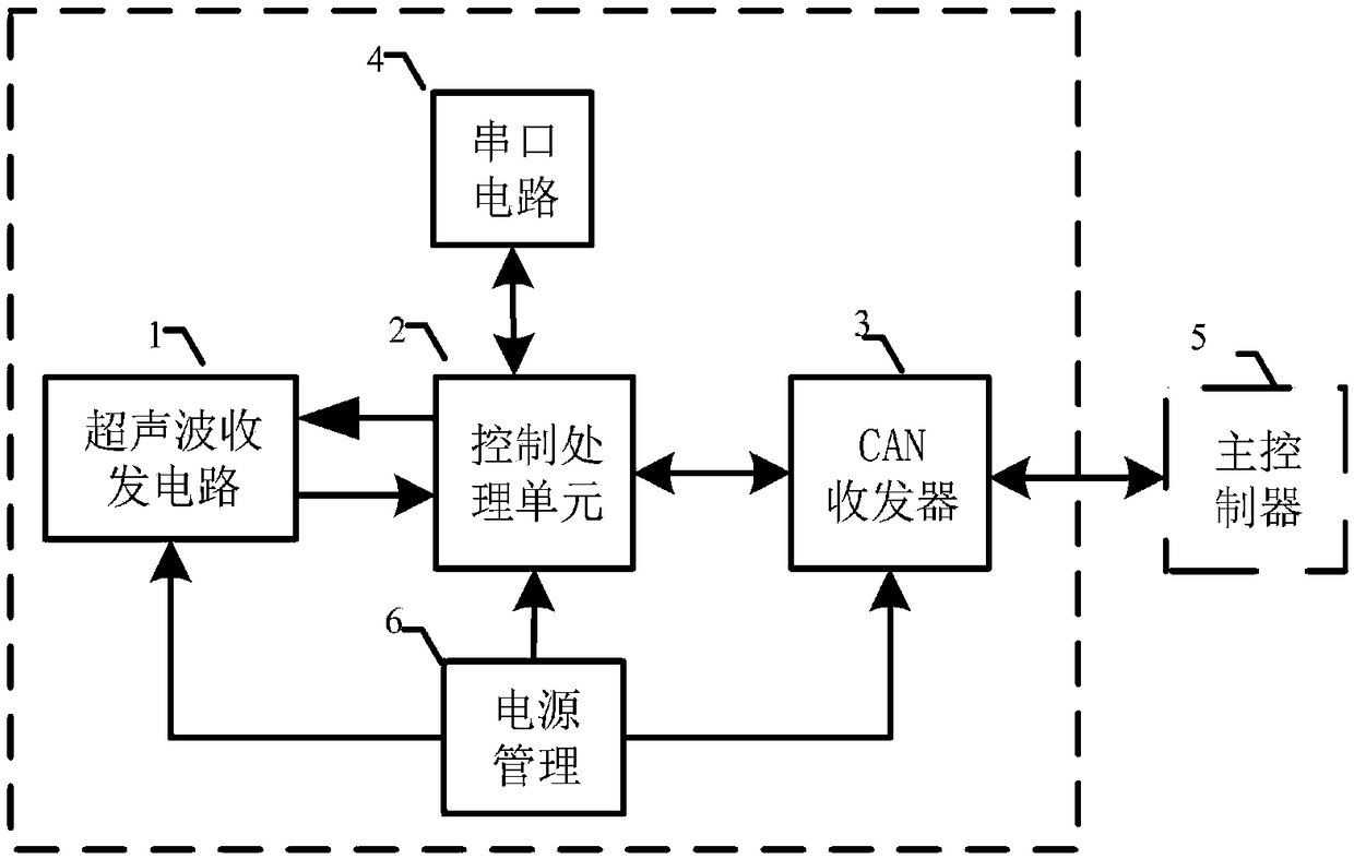
[0028] Such as image 3 As shown, the present invention provides an ultrasonic ranging and obstacle avoidance system, including a control processing unit 2, a serial port circuit 4, and a power management module 6, and also includes a multi-channel ultrasonic transceiver circuit 1, and a CAN transceiver circuit 3, wherein the control processing unit 2 are connected with ultrasonic transceiver circuit 1, serial port circuit 4, power management module 6 and CAN transceiver circuit 3 respectively, and described power management module 6 is used for the power supply of ultrasonic transceiver circuit 1, CAN transceiver circuit 3 and control processing unit 2, and described The control processing unit 2 is used to communicate with the main controller 5 and control the operation control of each module. The ultrasonic transceiver circuit 1 is used to detect obstacles and measure distances. The ultrasonic transceiver circuit 1 is composed of at least three independent ultrasonic transmi...


PUM


Abstract

The invention belongs to the field of ultrasonic range finding and particularly relates to an ultrasonic range finding obstacle avoidance system, comprising a control processing unit, a serial port circuit, a power management module, a multichannel ultrasonic transceiver circuit and a CAN transceiver circuit, wherein the control processing unit is connected with the ultrasonic transceiver circuit,the serial port circuit, the power management module, and the CAN transceiver circuit; the power management module is used for supplying power to the ultrasonic transceiver circuit, the CAN transceiver circuit, and the control processing unit; the control processing unit is configured to communicate with a main control system and to control the operation of each module; the ultrasonic transceivercircuit is used for detecting an obstacle and measuring a distance; an isolation transformer drives a ultrasonic transmission circuit to match an adaptive transmission pulse control algorithm, so that the detection distance of the ultrasonic range finding obstacle avoidance system is increased, a transducer is driven by ultra-high voltage, and the power for transmitting ultrasonic waves is sufficiently large, thereby achieving higher detection sensitivity than that of a conventional driving method.

Description

technical field [0001] The invention belongs to the field of ultrasonic distance measurement, and in particular relates to an ultrasonic distance measurement and obstacle avoidance system. Background technique [0002] With the development of sensor technology, in the field of ranging sensors, there are three commonly used technical solutions as follows: infrared ranging, laser ranging and ultrasonic ranging. The infrared ranging sensor has the advantages of low cost and simple circuit structure, but its detection distance is relatively short and its accuracy is low; the laser ranging sensor has the highest detection distance and accuracy among the above three sensors, but its use cost is too high; The effect of the ultrasonic ranging sensor is between the infrared and laser ranging schemes. It has a moderate detection distance and high detection accuracy, and has high adaptability to the environment, especially for transparent objects (such as glass, etc.) Effective detect...

Claims


Application Information

Patent Timeline
Patent Type & Authority Applications(China)
IPC IPC(8): G01S15/93G01S15/08G01S7/526
CPCG01S15/93G01S7/526G01S15/08
Inventor 黄山张尘曾奇李文
Owner CHENGDU EVENTEC SCI & TECH CO LTD
Why Eureka
Try Eureka