Drum vacuum dryer

A drum vacuum and dryer technology, applied in dryers, drying, non-progressive dryers, etc., can solve problems such as low heat energy use efficiency, leakage of heat pipes, and inability to use, and achieve energy saving and reduction of waste heat utilization. row, avoid impact swing, ensure the effect of negative pressure

Inactive Publication Date: 2019-02-26
程长春
View PDF0 Cites 1 Cited by
  • Summary
  • Abstract
  • Description
  • Claims
  • Application Information

AI Technical Summary

Problems solved by technology

[0002] Nowadays, in the processing and production fields of grain, food, chemical industry, medicine, agricultural and sideline products, pasture, etc., it is necessary to heat and dry the materials under vacuum conditions; the heat exchange of the drying chamber of the drum dryer on the market now mostly adopts pipe-type heat dissipation , Interlayer heating method for heat exchange and heat dissipation, but their radiators are large in size, small in heat dissipation area, and low in efficiency of heat energy use
We...

Method used


Image

  • Drum vacuum dryer
  • Drum vacuum dryer
  • Drum vacuum dryer

Examples


Embodiment 1

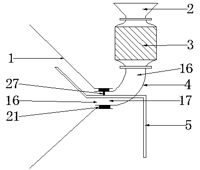
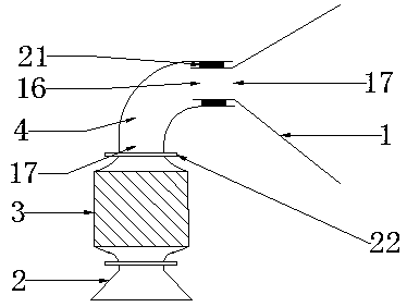
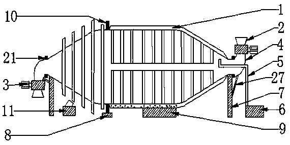
[0132] Such as figure 1 , figure 2 The drum vacuum dryer shown includes a vacuum drying chamber (1), a hopper (2), a discharge device (3), an elbow (4), an air duct (5), a vacuum unit (6), and a supporting wheel Support (7), driving device (8), heating device (9), gear ring (10), blower fan (11), sealing device (21), support (27).

[0133] The vacuum drying bin (1) has a feed inlet (16) and a feed outlet (17).

[0134] The supporting wheel bracket (7) includes a bracket and a supporting wheel.

[0135] 1. The supporting wheel is installed on the bracket.

[0136] 2. The support roller bracket (7) supports the vacuum drying chamber (1) and has a material inlet (16) and a material outlet (17).

[0137] Such as figure 1 , figure 2 , Figure 5 The shown elbow (4) is a metal elbow, and one end of the elbow (4) has a flange, and the other end does not have a flange to be a bare pipe.

[0138] The end of the elbow (4) without flange and the feed port (16) of the vacuum dryi...

Embodiment 2

[0220] The combined structure of the drum vacuum dryer shown in Embodiment 2 is the same as that described in Embodiment 1, and the similarities will not be repeated.

[0221] A drum vacuum dryer includes a vacuum drying chamber (1), a hopper (2), a discharge device (3), an elbow (4), an air duct (5), a vacuum unit (6), and a support wheel bracket (7 ), driving device (8), heating device (9), gear ring (10), fan (11), sealing device (21), bracket (27).

[0222] The vacuum drying bin (1) has a feed inlet (16) and a feed outlet (17).

[0223] The vacuum drying chamber (1) includes a heating chamber (12), a drying chamber (13), and a heat-conducting working fluid (15).

[0224] The heating chamber (12) is outside the drying chamber (13).

[0225] The drying bin (13) includes a bin body (26), a cooling standpipe, a heat pipe (14), a spiral blade, and a fixing strip (23).

[0226] The heat dissipation standpipe includes metal pipes (25) sealed at both ends, fins (24), and heat-c...


PUM

PropertyMeasurementUnit
Diameteraaaaaaaaaa
Heightaaaaaaaaaa

Abstract

The invention relates to a drum vacuum dryer. The drum vacuum dryer comprises a vacuum drying chamber, a hopper, a discharging device, an elbow, an air duct, a vacuum unit, a riding wheel bracket, a driving device, a heating device, a gear ring, a fan, a sealing device and a bracket. The vacuum drying chamber comprises a heating chamber, a drying chamber and a heat conducting working medium; the riding wheel bracket fixedly supports the vacuum drying chamber and is provided with a feed opening and a discharge opening. A flange-free end of the elbow and the feed opening and the discharge opening of the vacuum drying chamber are hermetically connected into a whole by the sealing device, and an end with a flange of the elbow is fixedly connected into a whole with the discharging device. Whenthe vacuum drying chamber is driven to rotate by the driving device, the air duct and the elbow are stationary, and the joint of the air duct and the elbow is sealed and airtight. The heat energy of the heating device heats a material, conducts heat to the material and radiates heat from the material through the heat conducting working medium, so that the heat conversion efficiency is high and theloss is small; the dried material is cooled in a cooling section, so that the material drying efficiency is improved, and the material drying effect is optimized. When one heat pipe is damaged and leaks, the use of the whole drum vacuum dryer is not affected.

Description

technical field [0001] The invention relates to a drum dryer, in particular to a drum vacuum dryer. Background technique [0002] Nowadays, in the processing and production fields of grain, food, chemical industry, medicine, agricultural by-products, pasture, etc., it is necessary to heat and dry the materials under vacuum conditions; the heat exchange of the drying chamber of the drum dryer on the market is mostly in the form of exhaust pipes. , Interlayer heating method for heat exchange and heat dissipation, but their radiators are large in size, small in heat dissipation area, and low in efficiency of heat energy use. Wet materials often form agglomerates under vacuum, which causes uneven drying of wet materials and affects the drying quality of materials. The drying chamber of the drum dryer on the market now has a high failure rate during use. The heat dissipation pipe in the drying chamber is worn by the material during the heat conduction and heat exchange process. ...

Claims


Application Information

Patent Timeline
IPC IPC(8): F26B5/04F26B11/04F26B21/00F26B23/10F26B25/00
CPCF26B5/04F26B11/044F26B11/0445F26B21/004F26B23/10F26B25/008
Inventor 程长春
Owner 程长春
Why Eureka
Try Eureka