


Quick Research
Generate reliable direction feasibility study reports for your R&D in just a few steps.

Technical Q&A
Discover and master advanced knowledge NOW. Basics, ideas, possibilities, all at once.

Find Solutions
As an expert in R&D theories, this can generate solutions to your technical problems instantly.

Evaluate Feasibility
Analyze your overall solution with one click, know your potential R&D risks in advance.

Monitor Landscape
Get weekly tech updates, stay abreast of the latest tech innovations and key insights.
Copper foil warpage reducing heat treatment device and method
A heat treatment device and heating device technology, applied in electrolysis process, electroforming, etc., can solve the problems of company loss, low work efficiency, high use and maintenance costs, and achieve the effects of reducing consumption, convenient operation, and widening the working space
- Summary
- Abstract
- Description
- Claims
- Application Information
AI Technical Summary
Problems solved by technology
Method used
Image

Examples
Embodiment 1
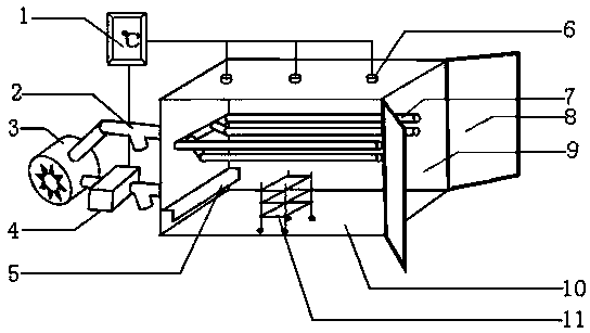
[0055] Example 1, such as figure 1 Shown:
[0056] A copper foil warping heat treatment device, comprising:
[0057] An oven 10 for placing copper foil;
[0058] A circulating air device for blowing wind from the first end of the oven 10 and extracting the wind from the second end of the oven 10;
[0059] A heating device for heating the wind blown into the oven 10 by the circulating air device; the heating device is installed on the air supply pipeline of the circulating air device.
[0060]According to the second law of thermodynamics (heat can be spontaneously transferred from a high-temperature object to a low-temperature object, but it is impossible to spontaneously transfer from a low-temperature object to a high-temperature object), the heat in the hot air passes through the first The end is transferred to the copper foil to play a heating role and lose part of the heat. Under the action of the circulating air device, the cold air is drawn into the heating device thr...
Embodiment 2
[0061] Example 2, such as figure 1 Shown:
[0062] The difference between this embodiment and embodiment 1 is:
[0063] The second end of the oven 10 is provided with an operation port 9 , and the operation port 9 is sealed by setting a sealing device 8 .
[0064] The copper foil can be put in and taken out through the operation port 9; and the sealing device 8 can ensure that the oven 10 is in a sealed state during operation.
Embodiment 3
[0065] Example 3, such as figure 1 Shown:
[0066] The difference between this embodiment and Embodiment 1 is that the circulating air device includes:
[0067] Circulation fan 3;
[0068] The air supply pipeline; the air outlet of the circulating fan 3 communicates with the first end of the oven 10 through the air supply pipeline;
[0069] 7 way exhaust pipe;
[0070] Exhaust duct 7; the exhaust duct 7 is installed inside the oven 10, the exhaust duct 7 includes a plurality of sub-exhaust ducts 7 with open first ends, and the first end of the sub-exhaust duct 7 is located inside the second end of the oven 10 , the air inlet of the circulating fan 3 communicates with the second ends of the plurality of sub-exhaust pipes 7 through the air-exhaust pipes 7.
[0071] The unique structural design of the exhaust duct 7 can ensure that the cold air located at the second end of the oven 10 can be quickly and comprehensively taken away; the combination of the circulation fan 3, the...
PUM
 Abstract
Description
Claims
Application Information
 - R&D Engineer
- R&D Manager
- IP Professional
- Industry Leading Data Capabilities
- Powerful AI technology
- Patent DNA Extraction
Browse by: Latest US Patents, China's latest patents, Technical Efficacy Thesaurus, Application Domain, Technology Topic, Popular Technical Reports.
© 2024 PatSnap. All rights reserved.Legal|Privacy policy|Modern Slavery Act Transparency Statement|Sitemap|About US| Contact US: help@patsnap.com