Cold water tank for marine high-power engine cylinder head production
An engine cylinder, high-power technology, applied in the field of cold water tanks for the production of marine high-power engine cylinder heads, can solve the problems of poor cooling effect, poor cooling efficiency, large volume, etc., to save costs and ensure the effect of cooling effect
- Summary
- Abstract
- Description
- Claims
- Application Information
AI Technical Summary
Problems solved by technology
Method used
Image
Examples
Embodiment 1
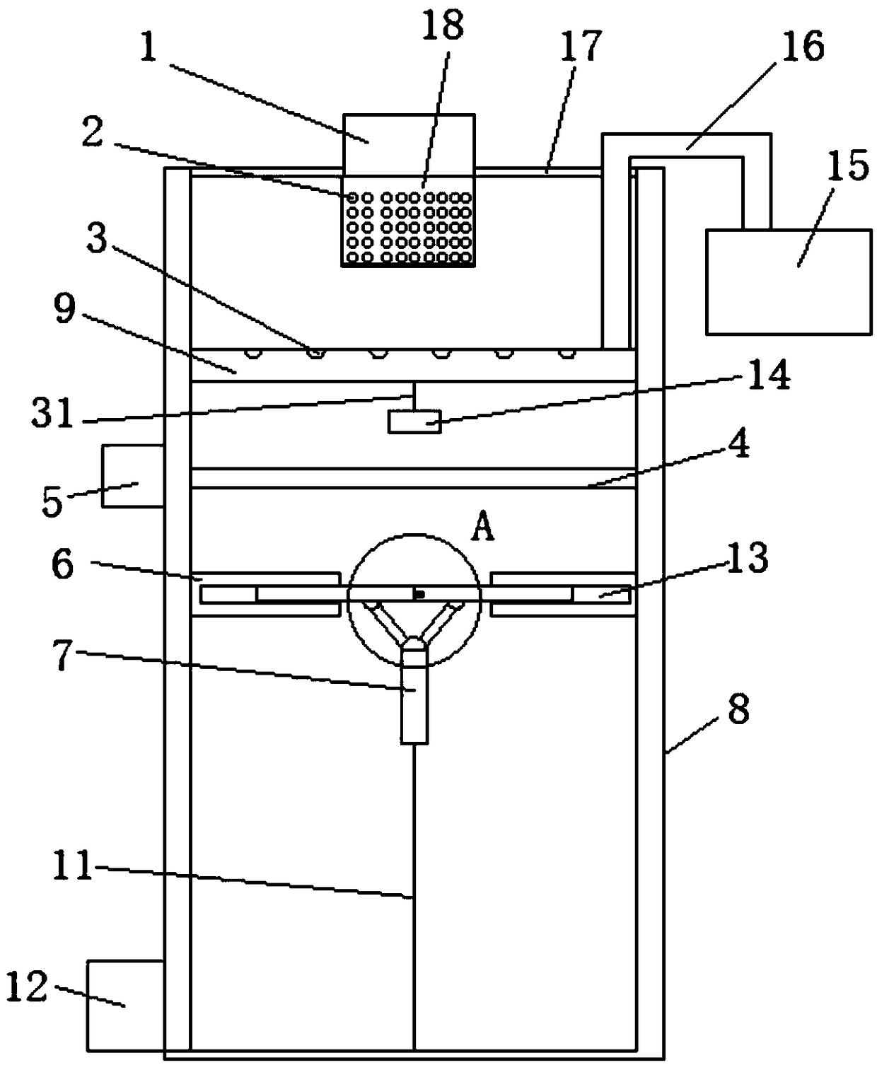
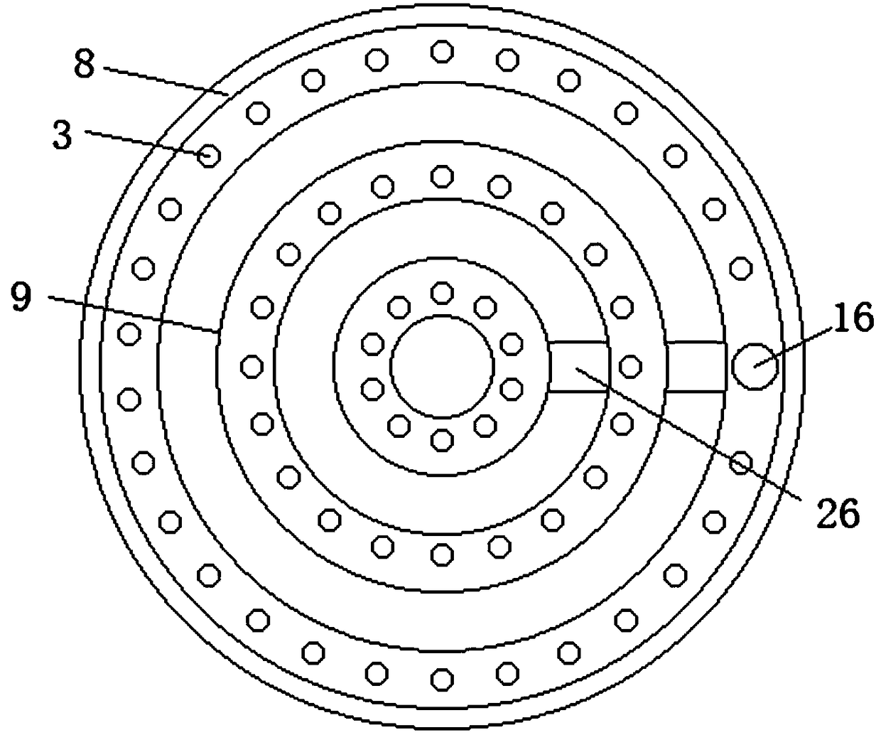
[0027] Embodiment 1, the cold water tank for the production of marine high-power engine cylinder head includes a tank body 8, the middle part of the upper end of the tank body 8 is provided with a water inlet pipe 1, and one side of the bottom of the tank body 8 is provided with a water outlet pipe 12, which is located at the inlet An aeration pipe 9 is arranged inside the tank body 8 at the bottom of the water pipe 1 , and a plurality of evenly distributed aeration holes 3 are arranged on the aeration pipe 9 .
[0028] Preferably, one side of the tank body 8 is provided with an aeration fan 15, the aeration fan 15 is provided with a guide tube 16, and the aeration fan 15 is connected with the aeration tube 9 through the guide tube 16, the The aeration pipe 9 is a ring-shaped pipe whose diameter gradually decreases, and the aeration pipe 9 is connected through a connecting pipe 26. The bottom of the aeration pipe 9 is provided with a connecting rod 31, and the bottom of the con...
Embodiment 2
[0032] The same as embodiment 1 is no longer repeated, and the difference with embodiment 1 is:
[0033] Preferably, the inner wall of the tank body 8 is provided with a number of symmetrical and evenly distributed slide bars 27, and the water dividing plate 6 is provided with a number of chutes 29 matched with the sliding bars 27, and the sides of the water dividing plate 6 are all A uniformly distributed second rubber layer 28 is provided, and the water separating plate 6 is slidably connected to the inner wall of the tank body 8 in the form of a sliding groove 29 and a sliding rod 27 . Through the slide bar 27 and the chute 29, the water diversion plate 6 can be effectively fixed to prevent the uneven force on the water diversion plate 6 from causing the water diversion plate 6 to turn over, resulting in the failure of water diversion. The setting of the second rubber layer 28 further The sealing ability of the water dividing plate 6 is greatly improved, and the interferenc...
Embodiment 3
[0035] The same as embodiment 1 is no longer repeated, and the difference with embodiment 1 is:
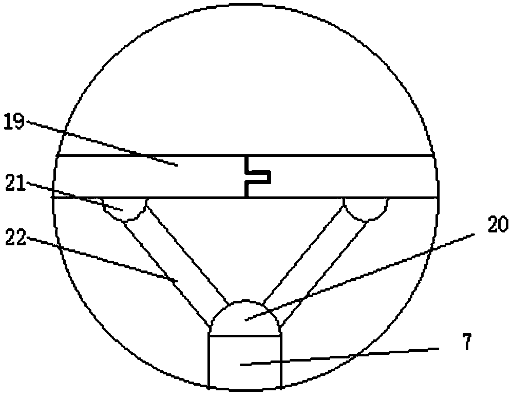
[0036] Preferably, the inside of the tank body 8 is provided with a matching and movably connected water diversion plate 6 , the middle of the water diversion plate 6 is provided with a communication hole 30 , and both sides of the communication hole 30 are provided with symmetrically distributed adjustment grooves 13 , the adjustment tank 13 is provided with the same size and symmetrically distributed water retaining plate 19, the center of the water diversion plate 6 is provided with an adjustment plate 7, and the upper end of the adjustment plate 7 is provided with a number of evenly distributed and The first living hinge 20 fixedly connected, both ends of the first living hinge 20 are provided with inclined and symmetrically distributed push rods 22, and the upper ends of the push rods 22 are provided with a second living hinge 21, the second One end of the loose-leaf hinge 21...
PUM
 Abstract
Description
Claims
Application Information
 - R&D Engineer
- R&D Manager
- IP Professional
- Industry Leading Data Capabilities
- Powerful AI technology
- Patent DNA Extraction
Browse by: Latest US Patents, China's latest patents, Technical Efficacy Thesaurus, Application Domain, Technology Topic, Popular Technical Reports.
© 2024 PatSnap. All rights reserved.Legal|Privacy policy|Modern Slavery Act Transparency Statement|Sitemap|About US| Contact US: help@patsnap.com


