
Non-contact substrate handling equipment

A non-contact, equipment-operated technology, used in the manufacture of conveyor objects, electrical components, semiconductor/solid-state devices, etc. problems, to shorten the cooling time, improve the accuracy of equipment, and avoid pollution.

Pending Publication Date: 2018-12-11
BEIJING NAURA MICROELECTRONICS EQUIP CO LTD
View PDF0 Cites 2 Cited by
  • Summary
  • Abstract
  • Description
  • Claims
  • Application Information

AI Technical Summary

Problems solved by technology

For example, for a non-contact substrate manipulation device in an epitaxial reactor, during the process of taking the sheet, the adsorption force formed at each air extraction hole acts on the front center of the substrate, and the adsorption force acting on the center of the substrate will make the The deformation of the substrate is too large, which is easy to form pressure damage; in addition, when taking the piece from the process chamber, the substrate still has a certain temperature, and there is a certain degree of adhesion between the grasping device of the equipment, and the substrate may not be able to It is absorbed very horizontally, which cannot guarantee smooth adsorption, resulting in the failure or drop of the film; for another non-contact substrate handling equipment in the epitaxial reactor, there are problems with the orientation and layout of the tangential hole of the suction cup. As a result, there are differences in the airflow size and rotating eddy current of each suction cup. When the wafer is sucked up, it will appear unstable, spin, and float, which cannot meet the needs of positioning, fixed-point pick-and-place, and transfer of wafers.

Method used


Image

  • Non-contact substrate handling equipment
  • Non-contact substrate handling equipment
  • Non-contact substrate handling equipment

Examples


Embodiment Construction

[0025] The present invention will be described more fully hereinafter with reference to the accompanying drawings, in which exemplary embodiments of the invention are illustrated. The following will clearly and completely describe the technical solutions in the embodiments of the present invention with reference to the accompanying drawings in the embodiments of the present invention. Obviously, the described embodiments are only some, not all, embodiments of the present invention. Based on the embodiments of the present invention, all other embodiments obtained by persons of ordinary skill in the art without making creative efforts belong to the protection scope of the present invention. The technical solution of the present invention will be described in various aspects in conjunction with the figures and embodiments below.

[0026] For the convenience of description below, the "left", "right", "upper" and "lower" referred to below are consistent with the left, right, upper ...


PUM


Abstract

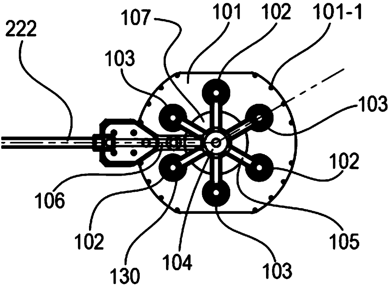
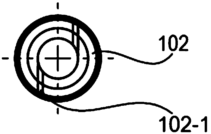
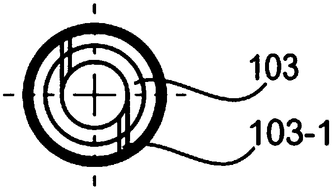
The invention discloses an embodiment of the present invention discloses a non-contact substrate operating apparatus, comprising: a gripping arm (222) and a gripping disk device; A plurality of suction sheet units (102, 103) arranged symmetrically in the center are arranged at the bottom of the grabbing disk device; The suction sheet unit (102, 103) is provided with a cavity and tangential holes (102-1, 103-1) communicating with the cavity; The grasping arm is internally provided with a vent pipe, and the grasping disc device is internally provided with an air cavity channel, and the vent pipeis communicated with the tangential holes (102-1, 103-1) through the air cavity channel, and the substrate is adsorbed by the pressure difference generated by the rotating vortex generated by the suction sheet unit. The device of the invention can eliminate the spin and deflection of the wafer and improve the accuracy of the device. The invention can avoid pollution, crushing and and the like tothe surface of the wafer, improve the quality of products. The device can be used to take and put tablets at high temperature so as to improve the capacity of equipments.

Description

technical field [0001] The invention relates to the technical field of semiconductor integrated manufacturing, in particular to a non-contact substrate operation device. Background technique [0002] In the field of semiconductor integrated circuit manufacturing, in order to generate epitaxially coated semiconductor wafers, the semiconductor wafers in the epitaxial reactor are usually used for epitaxial coating, and the deposition gas passes through the epitaxial reactor, which can be deposited on the surface of the semiconductor wafer. Deposit epitaxial material. In epitaxial reactors, wafer substrate transfer is very important. The wafer is generally circular with a front side and a back side. The front side of the wafer is the wafer surface that forms the integrated circuit structure; in addition, the area of ​​several millimeters at the edge of the wafer is not used to realize the integrated circuit manufacturing. Therefore, it is very important to protect the front si...

Claims


Application Information

Patent Timeline
Patent Type & Authority Applications(China)
IPC IPC(8): H01L21/683H01L21/677
CPCH01L21/67742H01L21/6838
Inventor 弓利军
Owner BEIJING NAURA MICROELECTRONICS EQUIP CO LTD
Learn More