
Lens detection device used on stream line

A detection device and assembly line technology, applied in the direction of transmittance measurement, etc., can solve the problems of high error rate and low efficiency of light transmittance detection of batches of lenses, and achieve the effects of avoiding pollution, improving efficiency and reducing pollution

Inactive Publication Date: 2019-02-15
郑期壮
View PDF1 Cites 4 Cited by
  • Summary
  • Abstract
  • Description
  • Claims
  • Application Information

AI Technical Summary

Problems solved by technology

[0005] The present invention aims at the above-mentioned defects existing in the prior art, and solves the problems of low transmittance detection efficiency and high error rate of batches of lenses in the prior art

Method used


Image

  • Lens detection device used on stream line
  • Lens detection device used on stream line
  • Lens detection device used on stream line

Examples


Embodiment 1

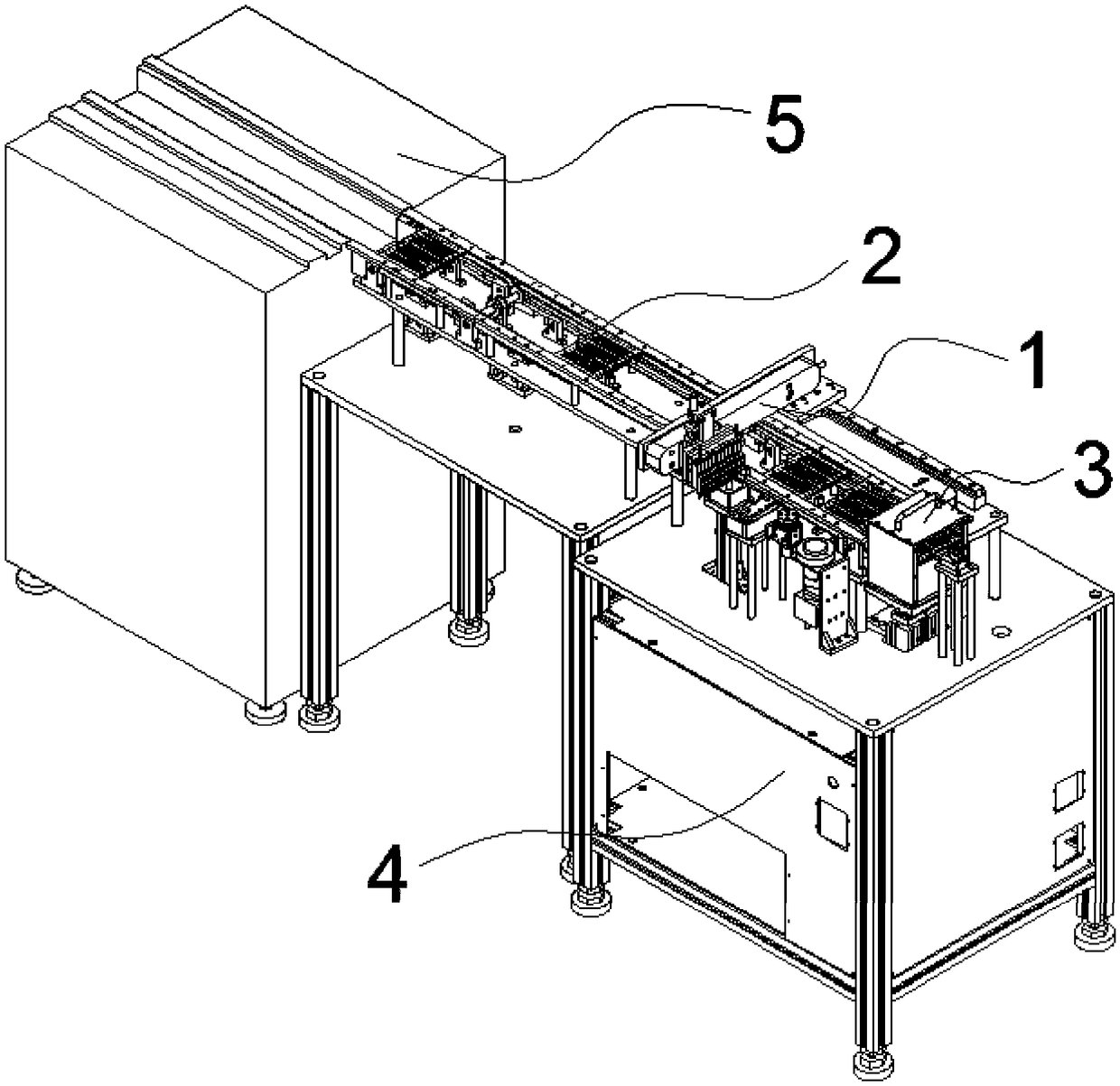
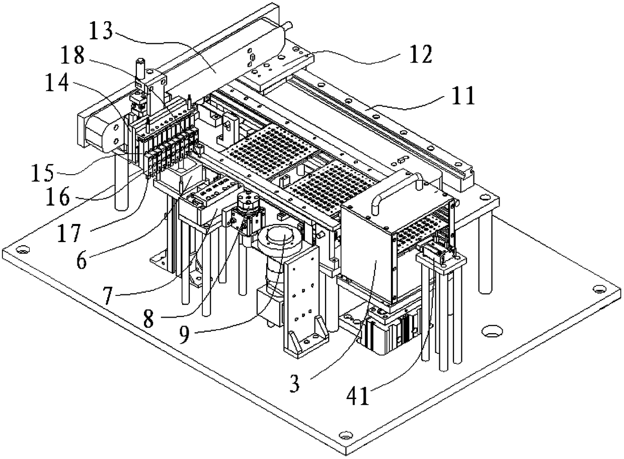
[0033] Such as Figure 1-6 As shown, it includes: removal part 1, conveyor belt 2, storage part 3, drive box 4, feeding part 5, collection part 6, cleaning part 7, detection part 8, control part 9, slide rail 11, sliding base Seat 12, cross arm 13, traverse slider 14, first cylinder group 15, second cylinder group 16, suction cup 17, positioning device 18, plate positioning device 41, lifting device 42, connecting tray 43, support seat 411, Abutting cylinder 412, abutting block 413, cylinder 71, dust collecting plate 72, card slot 73, fixing seat 81, fixing slot 82, light transmission hole 83, rotating shaft 84 and collecting part 85;

[0034] Such as figure 1 As shown, one end of the conveyor belt 2 abuts against the feeding part 5, and the feeding part 5 transports the lens to be inspected to the conveyor belt 2 by shaking; the other end of the conveyor belt 2 abuts against the storage part 3, and the storage part 3 3 is used to collect and store the detected lenses; the b...

Embodiment 2

[0043] Compared with Embodiment 1, Embodiment 2 is based on Embodiment 1. A collection unit 6 is set on one side of the conveyor belt 2. After the light transmittance of the lens is detected, the removal unit 1 sucks the lens and moves to the collection unit. Above the part 6, unqualified lenses are put into the collection part 6, which improves the recycling efficiency of unqualified lenses, and also prevents unqualified lenses from being mixed into qualified lenses, affecting the use effect of the lenses.


PUM


Abstract

The invention discloses a lens detection device used on a stream line and relates to the technical field of steam line lens detection equipment. The lens detection device comprise a moving part, a conveyer belt, a storage part and a feeding part, wherein one end of the conveyer belt is propped against the feeding part; the feeding part is used for conveying a lens to be detected to the conveyer belt through vibration; the other end of the conveyer belt is propped against the storage part; the storage part is used for collecting and storing detected lenses; a driving tank is arranged at the bottom of the storage part; the driving tank is used for driving the storage part to be lifted up and down; the conveyer belt is used for a lens which is received from the feeding part and is to be detected to the storage part; a cleaning part, a detection part and a control part are arranged on one side of the conveyer belt; the cleaning part is used for cleaning the lens to be detected; the detection part is used for detecting the light permeability of the lens; the control part is used for controlling movement of the conveyer belt and the moving part. Due to adoption of the moving part, the lens does not need to be moved manually, lens contamination can be reduced, and the detection result of the lens is not affected.

Description

technical field [0001] The invention relates to the technical field of assembly line lens inspection equipment, in particular to an assembly line lens inspection device. Background technique [0002] At present, after the lenses are coated at high temperature, they are manually sorted, and the coated lenses are sorted on the material board, and then the material board with the lenses is sent to the inspection department for inspection. This kind of full inspection relies on manual work. The method of sampling the lenses on the material board is inefficient, has a high error rate, and is easy to cause damage to the lenses during the inspection process. [0003] For example, Chinese patent CN201820314598 discloses an optical glass detection device, including a detection box, a conveyor belt body, a base and a glass light transmittance detector, the base is provided with a power storage box, and the top of the base is provided with a shock-absorbing layer , the top of the shoc...

Claims


Application Information

Patent Timeline
IPC IPC(8): G01N21/59
CPCG01N21/59
Inventor 漆金枝
Owner 郑期壮
Learn More