
Annealing device capable of preventing sparking and eliminating resistance for power cable

A technology for power cables and annealing devices, applied in furnaces, heat treatment equipment, heat treatment furnaces, etc., can solve problems such as cable surface burns, inconsistent upper resistance, and sparking, so as to improve surface quality, ensure consistency, and reduce sparking The effect of the phenomenon

Active Publication Date: 2019-02-15
JUNLANG ELECTRICAL CO LTD
View PDF6 Cites 0 Cited by
  • Summary
  • Abstract
  • Description
  • Claims
  • Application Information

AI Technical Summary

Problems solved by technology

[0003] During the cable annealing process of the contact brush transmission high-current annealing machine, the electrode wheel inside the device is in contact with the cable. After a long working time, the contact surface has poor contact and occasionally sparks, which will cause the cable surface to burn and affect the cable surface. quality, and during the long-term working process of the electrode wheel, the upper resistance of the electrode wheel will be inconsistent. A slight increase in resistance will cause the cable to be stretched, and the formed wire diameter of the cable will be inconsistent before and after, and this section of cable will become a defective product.

Method used


Image

  • Annealing device capable of preventing sparking and eliminating resistance for power cable
  • Annealing device capable of preventing sparking and eliminating resistance for power cable
  • Annealing device capable of preventing sparking and eliminating resistance for power cable

Examples


Embodiment

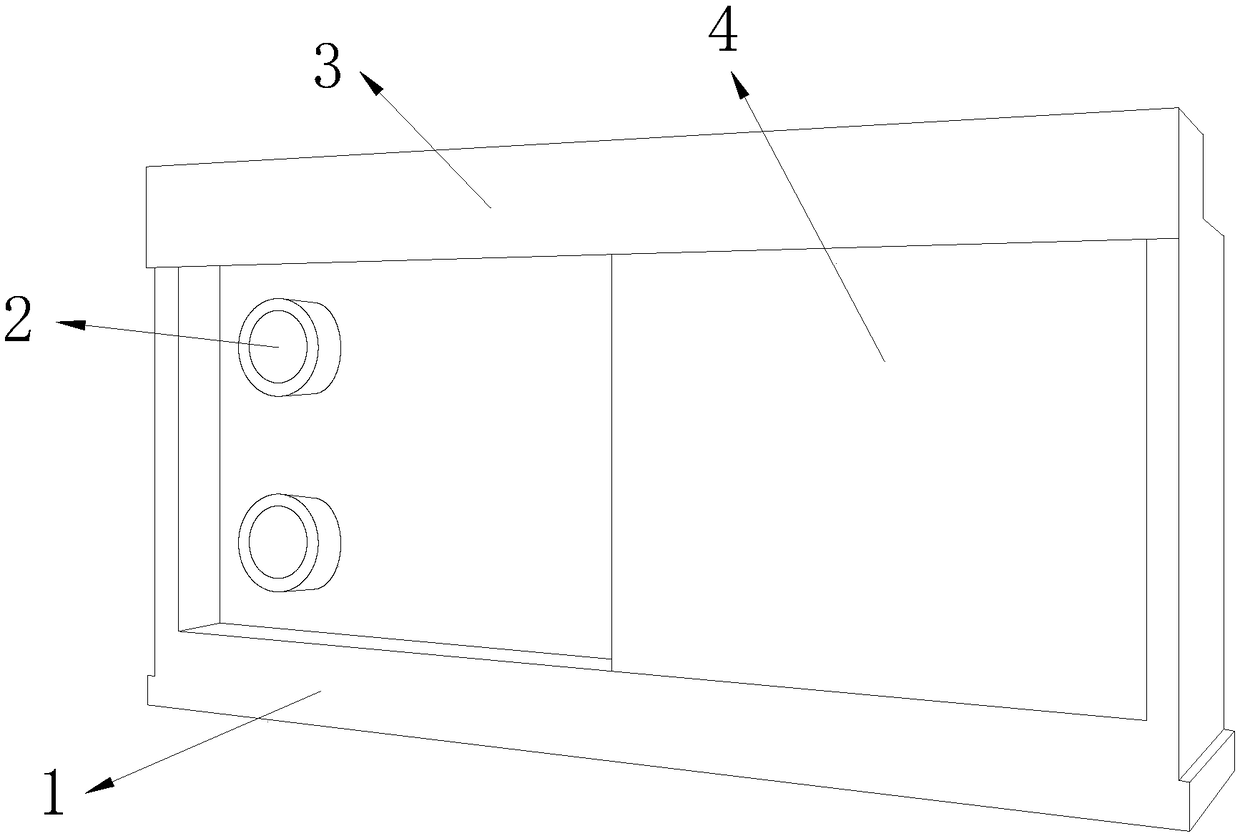
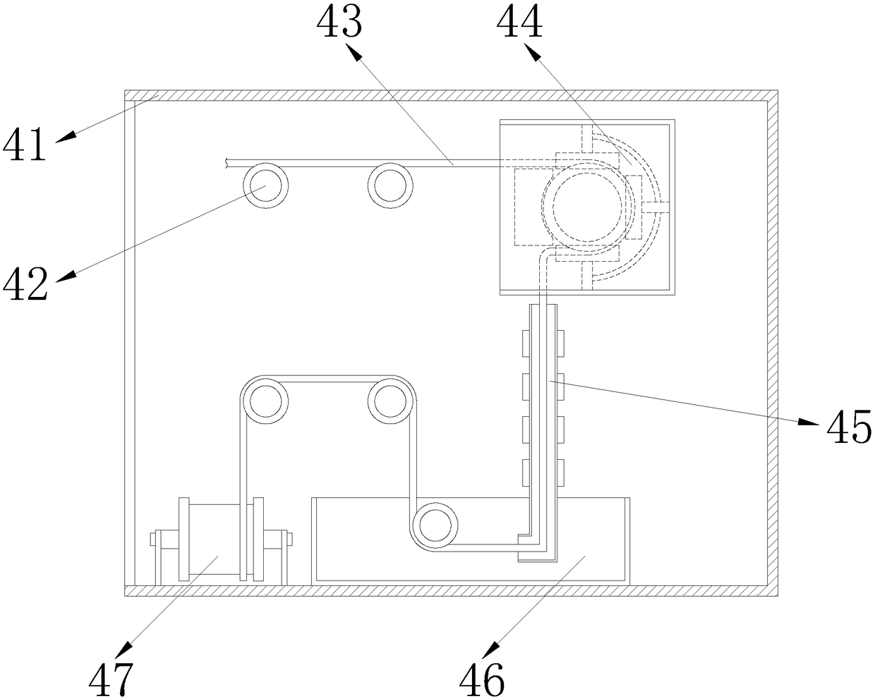
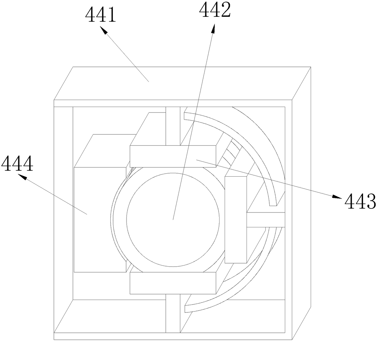
[0020] see Figure 1-Figure 7 , the present invention is an annealing device for anti-ignition and resistance resistance for power cables. Disk 2, the top seat 3 is fixedly installed on the top of the reinforced base 1, the pay-off disk 2 is located at the left end of the contact brush annealing machine 4, and the bottom end of the contact brush annealing machine 4 is fixedly installed on the reinforced base 1, so The top of the contact brush annealing machine 4 is fixedly connected with the top seat 3, and the contact brush annealing machine 4 includes a protective shell 41, a transmission wheel set 42, a cable 43, an electrode wheel mechanism for eliminating ignition 44, an annealing pipe 45, and a cooling box 46. ​​The take-up reel 47, the inside of the protective shell 41 is provided with a drive wheel set 42, the drive wheel set 42 is connected to the cable 43, the cable 43 is connected to the pay-off reel 2, and the ignition electrode is eliminated The wheel mechanism 4...


PUM


Abstract

The invention discloses an annealing device capable of preventing sparking and eliminating resistance for a power cable. The annealing device structurally comprises a reinforcing base, pay-off discs,a top seat and a contact electric brush annealing machine. The pay-off discs are arranged at the upper end of the reinforcing base, the top seat is fixedly mounted at the top end of the reinforcing base, the pay-off discs are located at the left end of the contact electric brush annealing machine, the bottom end of the contact electric brush annealing machine is fixedly mounted on the reinforcingbase, and the top end of the contact electric brush annealing machine is fixedly connected with the top seat. The cable is extruded through extrusion cable contact mechanisms, it is guaranteed that contact between the cable and an electrode wheel is better, the sparking phenomenon is reduced, meanwhile, sparking can be eliminated through sparking eliminating electrodes, and the surface quality ofthe cable is improved. In the rotating process of the electrode wheel, when the resistance is increased, heat generated by the electrode wheel is increased, at the moment, a hot air thrust mechanism absorbs hot air and applies certain thrust to the electrode wheel, the electrode wheel normally rotates, it is guaranteed that the resistance is unchanged, the cable is prevented from being stretched,and it is guaranteed that the forming wire diameter of the cable is consistent front and back.

Description

technical field [0001] The invention relates to the field of cable processing equipment, in particular to an annealing device for preventing ignition and eliminating resistance. Background technique [0002] After the power cable conductor is cold-drawn, there is a hardening phenomenon. To eliminate the cold-drawing hardening phenomenon and increase the elongation, it must be annealed to eliminate internal stress and defects. Among them, the contact brush transmission high-current annealing machine can Realizing high-speed continuous annealing and relatively energy-saving, as one of the commonly used annealing treatment devices, but the current contact brush transmission high-current annealing machine has the following disadvantages: [0003] During the cable annealing process of the contact brush transmission high-current annealing machine, the electrode wheel inside the device is in contact with the cable. After a long working time, the contact surface has poor contact and...

Claims


Application Information

Patent Timeline
Patent Type & Authority Applications(China)
IPC IPC(8): C21D9/52C21D1/30
CPCC21D1/30C21D9/52
Inventor 孙岳明
Owner JUNLANG ELECTRICAL CO LTD
Learn More