Towing machine with sliding device

A skid device and towing machine technology, applied in the field of towing machine equipment, can solve the problems affecting the safety and reliability of ship operation, the inability to effectively maintain the stability of traction force, and the poor stability of traction force output, so as to improve reliability and safety , Improve the stability of equipment operation, and the effect of wide adjustment range

Inactive Publication Date: 2019-02-15
JIANGSU MASADA HEAVY INDS
View PDF11 Cites 0 Cited by
  • Summary
  • Abstract
  • Description
  • Claims
  • Application Information

AI Technical Summary

Problems solved by technology

[0002] The cable towing machine is the main cable retracting mechanism of various ships at present. It is used in a huge amount and is of great significance to the operation safety of the ship. However, it is found in actual use that although the current towing machine equipment can meet the needs of use, the structure Compared with the load, the degree of automation of operation is relatively low, and the current towing machine equipment often lacks effective traction adjustment capabilities, resulting in poor traction output stability during cable traction operations, and the traction force cannot be flexibly adjusted according to the needs of use. At the same time, it is impossible to effectively maintain the stability of the traction force. In addition, it is not possible to quickly separate and connect the hydraulic drive mechanism and the traction mechanism of the towing machine according to the needs of the use, resulting in a problem in the cable traction operation. , especially when towing in sea areas with strong winds and waves, due to rapid release of hydraulic brakes or breakage of cables, it is easy to cause damage to hydraulic motors or hulls, which seriously affects the safety and reliability of ship operations. Therefore, for this One problem, there is an urgent need to develop a brand-new towing machine equipment to meet the needs of actual use

Method used


Image

  • Towing machine with sliding device

Examples


Embodiment Construction

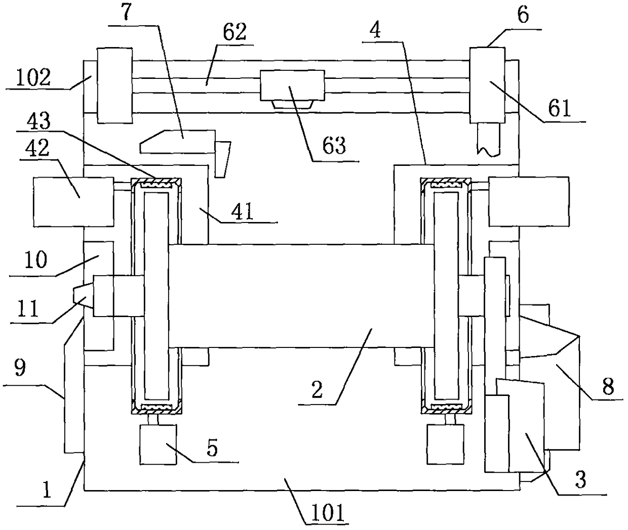
[0013] Attached below figure 1 The present invention will be described in detail with specific embodiments.

[0014] In order to make the technical means, creative features, goals and effects achieved by the present invention easy to understand, the present invention will be further described below in conjunction with specific embodiments.

[0015] Such as figure 1 The towing machine with a skid device includes a load bearing base 1, a cable drum 2, a hydraulic motor drive device 3, a hydraulic brake 4, a cable discharge device 6, a force measuring device 5, and a rope length measuring device 7 , the hydraulic station 8 and the control circuit 9, wherein the carrier base 1 includes a base plate 101 and a side plate 102, the side plate 102 is located at the front end of the base plate 101, and is vertically distributed with the base plate 101, and the base plate 101 and the side plate 102 are both Frame structure, the twisted cable drum 2 is installed on the upper end surface...


PUM


Abstract

The invention relates to a towing machine with a sliding device. The towing machine comprises a bearing machine seat, a warping drum, a hydraulic motor driving device, hydraulic brakes, a cable discharging device, a force measuring device, a rope length measuring device, a hydraulic station and a control circuit. The bearing machine seat comprises a bottom plate and a side plate, and the warping drum is mounted on the upper end surface of the bottom plate through bearing columns. The hydraulic brakes are symmetrically distributed at both ends of the warping drum, and include bases, hydraulic driving mechanisms and brake pads. The hydraulic motor driving device is connected to one side of the warping drum through a transmission mechanism. The cable discharging device is located on the sideplate, and comprises a transmission wheel set, a guiding shaft and a guiding sliding block. The hydraulic station and the control circuit are both mounted on the bottom plate. The towing machine withthe sliding device is simple in structure, flexible and convenient to use, good in universality, stable in braking force output, wide in adjustment range and flexible in adjustment, and can effectively avoid the occurrence of a hydraulic motor or hull damage accident caused by the rapid release of the hydraulic brakes or the cable breakage of the towing operation, thereby greatly improving the reliability and safety of the towing operation.

Description

technical field [0001] The invention relates to a cable winch device, specifically a drag winch with a slipping device. Background technique [0002] The cable towing machine is the main cable retracting mechanism of various ships at present. It is used in a huge amount and is of great significance to the operation safety of the ship. However, it is found in actual use that although the current towing machine equipment can meet the needs of use, the structure Compared with the load, the degree of automation of operation is relatively low, and the current towing machine equipment often lacks effective traction adjustment capabilities, resulting in poor traction output stability during cable traction operations, and the traction force cannot be flexibly adjusted according to the needs of use. At the same time, it is impossible to effectively maintain the stability of the traction force. In addition, it is not possible to quickly separate and connect the hydraulic drive mechani...

Claims


Application Information

Patent Timeline
Patent Type & Authority Applications(China)
IPC IPC(8): B65H75/42
Inventor 黄志峰冯永奕邵振华何海浪贺光辉郭强董飞
Owner JIANGSU MASADA HEAVY INDS
Why Eureka
Try Eureka