
Self-adaptive processing method for front and rear edges of aero-engine stator blade

A technology for aero-engines and stator blades, applied in metal processing equipment, manufacturing tools, milling machine equipment details, etc., can solve the problems of obvious cutting, flat head, edge trimming, etc., achieve strong versatility and practicability, and reduce manual intervention , The effect of saving processing costs

Inactive Publication Date: 2019-02-15
SHENYANG LIMING AERO-ENGINE GROUP CORPORATION
View PDF6 Cites 6 Cited by
  • Summary
  • Abstract
  • Description
  • Claims
  • Application Information

AI Technical Summary

Problems solved by technology

[0002] The front and rear edges of aero-engine stator blades without mounting plates are mainly processed by manual polishing and CNC machining. With manual polishing, the dimensional accuracy and edge shape of the front and rear edges are difficult to guarantee, and problems such as edge chamfering and flat head often occur; With the CNC machining method, the dimensional accuracy and edge shape of the front and rear edges can be guaranteed. However, since the blade surface has been processed, the edge part and the blade body are obviously connected, and there is still a risk of destroying the dimensional accuracy in supplementary processing.
[0003] Researchers at home and abroad have made great breakthroughs in the field of adaptive machining. In terms of spatial geometry adaptation, they have initially mastered technologies such as measurement, model reconstruction, correction, and registration, and realized integration in CNC machining of related products in the automotive and shipbuilding fields. However, in the aviation field, there is no mature adaptive processing repair method in the production and processing process of the leading and trailing edges of stator blades without mounting plates

Method used


Image

  • Self-adaptive processing method for front and rear edges of aero-engine stator blade

Examples


Embodiment Construction

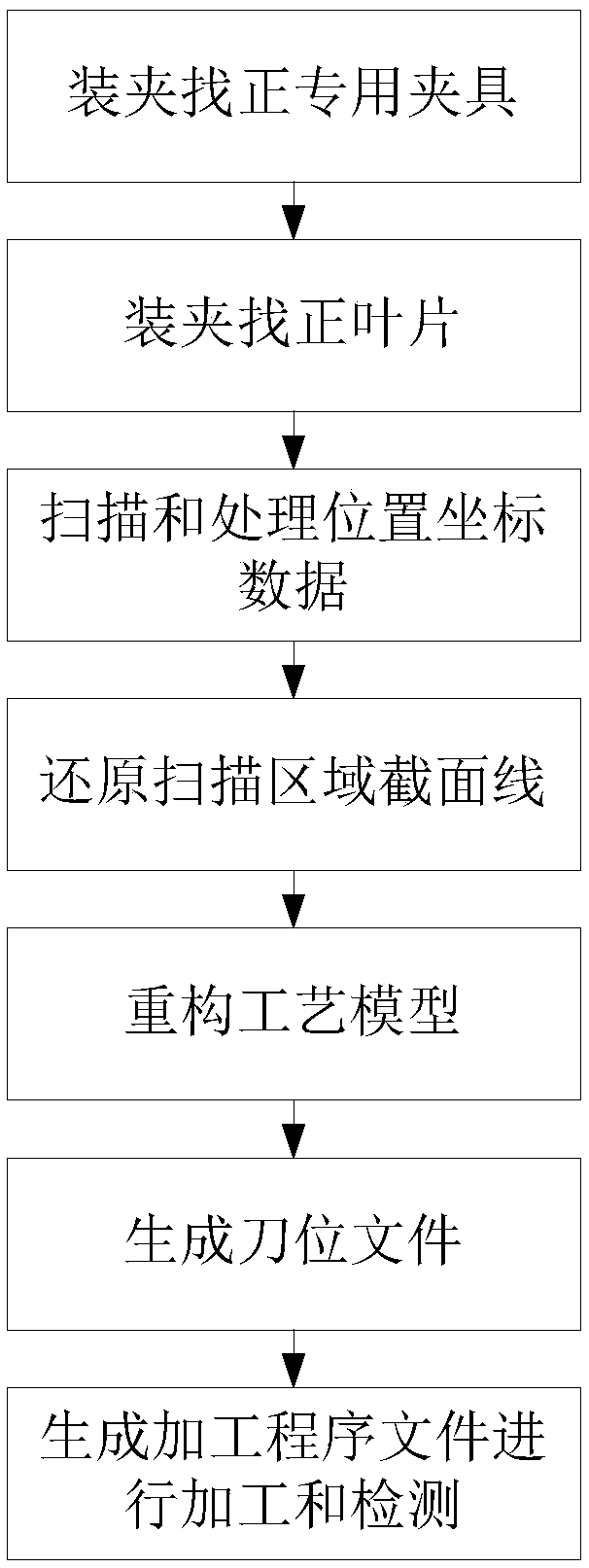
[0033] An adaptive processing method for leading and trailing edges of an aeroengine stator blade of the present invention adopts spatial geometry adaptive processing technology, collects coordinate data in corresponding areas of leading and trailing edges through a non-contact measurement system, and processes the data. According to the scanning data and theoretical model, the process model required for processing is constructed, and an adaptive tool position file is generated for the current part to complete the processing of the blade. The present invention will be further described below with reference to the accompanying drawings and embodiments.

[0034] A method for self-adaptive processing of leading and trailing edges of an aeroengine stator blade of the present invention comprises the following steps:

[0035] Step 1. Clamping and aligning the special fixture: clamp the blade adaptive processing special fixture on the machine tool and align it, specifically:

[0036...


PUM


Abstract

The invention discloses a self-adaptive processing method for front and rear edges of an aero-engine stator blade. The self-adaptive processing method adopts a space geometry self-adaptive processingtechnology, acquires coordinate data in corresponding areas of front and rear edges through a non-contact type measuring system, and processes the data. A needed process model is constructed and processed according to scanning data and a theoretical model, and a self-adaptive tool location file is generated according to a current part, so that processing of the blade is completed. The method breaks through the conventional manual polishing way and the numerical-control processing way, increases a processing qualification rate of the front and rear edges of the blade, reduces processing cost, solves the problems that front and rear edges of mounting-plate-free stator blades are unqualified in dimension precision and edge formation in a processing process, a jointed tool on the processed surface is difficult to eliminate, and the like; and the optimized processing process is stable, and a great deal of manual intervention is reduced. The self-adaptive processing method has relatively strong universality and practicability.

Description

technical field [0001] The invention belongs to the technical field of aerospace numerical control processing, and relates to an adaptive processing method for the leading and trailing edges of an aeroengine stator blade. Background technique [0002] The front and rear edges of aero-engine stator blades without mounting plates are mainly processed by manual polishing and CNC machining. With manual polishing, the dimensional accuracy and edge shape of the front and rear edges are difficult to guarantee, and problems such as edge trimming and flat ends often occur; With the CNC machining method, the dimensional accuracy and edge shape of the front and rear edges can be guaranteed. However, since the blade surface has been processed, the edge part and the blade body are obviously connected by a knife, and there is still a risk of destroying the dimensional accuracy during reprocessing. [0003] Scholars at home and abroad have made great breakthroughs in the field of adaptive ...

Claims


Application Information

Patent Timeline
IPC IPC(8): B23C3/18B23C9/00
CPCB23C3/18B23C9/00
Inventor 高见李美荣梁永收周鑫兰影铎
Owner SHENYANG LIMING AERO-ENGINE GROUP CORPORATION
Learn More