
Casting method for aluminum alloy engine shell

An engine casing and aluminum alloy technology, applied in the field of aluminum alloy casting, can solve the problems of inapplicability, high price, high labor intensity, etc., and achieve the effects of saving production costs, improving strength, and ensuring quality

Active Publication Date: 2019-02-15
YANGZHOU FENG MING METAL PROD
View PDF7 Cites 1 Cited by
  • Summary
  • Abstract
  • Description
  • Claims
  • Application Information

AI Technical Summary

Problems solved by technology

First of all, it is inconvenient to move. Sometimes the product needs to be transported for a long distance when it is put into the sand shower tank. The labor intensity of the operator is high, and the operation risk is high.
Secondly, the operation is inconvenient. Due to the limited space, during the sand shower operation, the product needs to be turned over, so that the different slurry surfaces face up to receive the sand shower. A little carelessness when turning over can easily break the product or the gating system; even if the operator is very careful , the damage rate is still high, and often needs to be repaired; the operator feels tired, the labor intensity is high, and the product scrap rate is high
[0006] The traditional core shooter can evenly inject molding sand into the sand box for pre-compacting, but the core shooter has a large structure and is expensive, and the ejected sand flies along a straight line, which is only suitable for filling the sand in the sand box. For the copper tube Small diameter and curved channels of the cavity, it is not applicable

Method used


Image

  • Casting method for aluminum alloy engine shell
  • Casting method for aluminum alloy engine shell
  • Casting method for aluminum alloy engine shell

Examples


Embodiment Construction

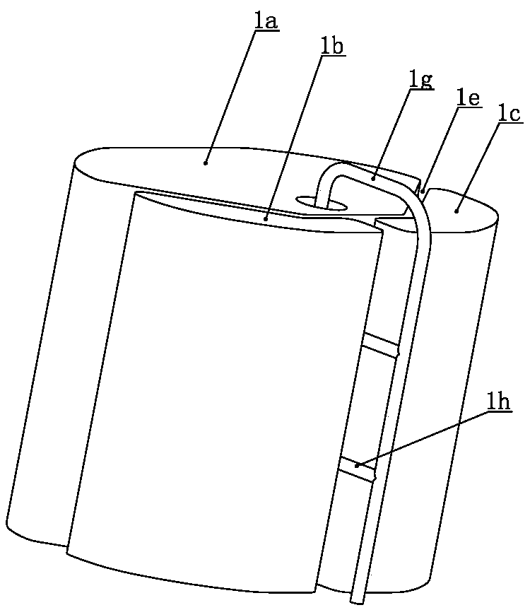
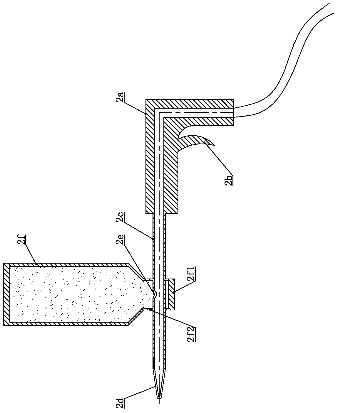
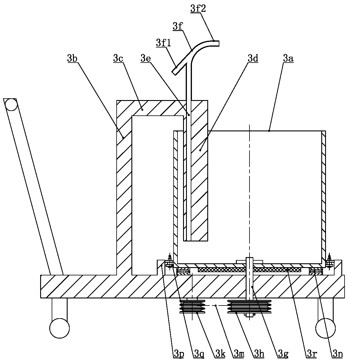
[0035] Such as Figure 1 to Figure 14 As shown, the casting method of the aluminum alloy engine casing of the present invention comprises the following steps in turn: (1) the copper tube is made into the same shape as the oil passage 7d on the engine casing 7 through a mold, and the sand filling tool for the curved hole is used to fill the copper tube into the copper tube. The cavity is filled with coated sand, and then the port of the copper tube is closed; (2) the core 1 is made with the same shape as the inner cavity of the engine casing 7; (3) the copper tube is combined with the core 1 and fixed, as figure 1 Shown; (4) Dip the core 1 into the slurry dipping machine and dip the refractory coating, after taking it out, spray the refractory sand on the surface of the core 1 through the sand pouring machine, then dip the slurry, then pour the sand, repeat several layers to get the inner mold shell, The inner mold shell is dewaxed after being air-dried, and then baked at high ...


PUM


Abstract

The invention relates to a casting method for an aluminum alloy engine shell. The casting method sequentially includes the following steps that firstly, red copper pipes are manufactured to be in a shape the same with that of shell oil ways, and the red copper pipes are sealed after being filled with precoated sand; secondly, cores are manufactured; thirdly, the red copper pipes and the cores arecombined and fixed; fourthly, the cores are subjected to pulp dipping and then sand pouring, then pulp dipping is conducted again and sand pouring is conducted again, the operation is conducted repeatedly by multiple layers, inner die shells are obtained, dewaxing is conducted after the inner die shell is subjected to air drying, and high-temperature roasting sizing is conducted; fifthly, sand molds are manufactured in sand boxes, cavities coincide with the outer wall of the engine shell in shape, and casting systems are arranged in the sand molds; sixthly, the inner die shells are put into the cavities of the sand molds, then mold assembling is conducted; seventhly, aluminum alloy liquid is injected into the cavities till mold filling is completed; eighthly, after cooling forming, the engine shell is obtained, spare parts are removed, and the precoated sand in all the red copper pipes is removed; ninth, the shell engine is immersed in a dilute nitric acid solution, and the red copperpipes are corroded and form oil ways. By means of the casting method, the manufacturing cost is low, consumption of raw materials is low, the product quality is good, manufactured hole ways are smoothand reliable, and the yield is high.

Description

technical field [0001] The invention relates to a casting process, in particular to a casting method of an aluminum alloy engine casing, and belongs to the technical field of aluminum alloy casting. Background technique [0002] The structure of castings is ever-changing, especially for engine casings. There are many cavities in casing castings, and there are oil passages in the casing wall. The diameter of the oil passages is small and the shape is curved. Ordinary sand cores are made of quartz sand, coated sand, resin sand or red sand, etc., but the strength and toughness cannot be balanced; when encountering the oil passage with a small diameter in the engine shell, the above materials cannot be used to make sand cores. Because of the limitations of the hardness and toughness of the sand itself. If the hardness of the sand core is too hard, it will be difficult to clean the sand after casting, and if the hardness is too low, it will be difficult to form the sand core. T...

Claims


Application Information

Patent Timeline
IPC IPC(8): B22C9/24B22C9/02
CPCB22C9/02B22C9/24
Inventor 徐凯川眭怀明王堃
Owner YANGZHOU FENG MING METAL PROD
Learn More