A desulfurization and denitrification purification device for industrial boiler flue gas separation in coal power plants

A desulfurization and denitrification, industrial boiler technology, applied in separation methods, dispersed particle separation, climate change adaptation and other directions, can solve the problem of increasing the purchase and production costs of desulfurization and denitrification towers, poor pipeline transportation efficiency, and poor flue gas desulfurization and denitrification efficiency. and other problems, so as to facilitate timely replacement and processing, increase the firmness and stability of the connection, and facilitate dredging and cleaning.

Active Publication Date: 2021-02-09
江苏绿叶环境工程集团有限公司
View PDF4 Cites 0 Cited by
  • Summary
  • Abstract
  • Description
  • Claims
  • Application Information

AI Technical Summary

Problems solved by technology

[0004] The purpose of the present invention is to provide a desulfurization and denitrification purification device for industrial boiler flue gas separation for coal power plants, to solve the problem in the modern use of the desulfurization and denitrification purification device for boiler flue gas separation proposed in the background technology, the transmission pipeline adopts an integral model, It is not convenient for users to clean and dredge the inside of the pipeline, which makes the pipeline prone to blockage after long-term use, making the transportation efficiency of the pipeline poor, and after a long-term use of the desulfurization and denitrification tower, dirt is prone to appear on the inner wall , so that the chemical medium is easy to react with the chemical substances in the dirt on the inner wall of the desulfurization and denitrification, which makes the desulfurization and denitrification efficiency of the flue gas poor, and it is easy to increase the purchase and production costs of the desulfurization and denitrification tower

Method used


Image

  • A desulfurization and denitrification purification device for industrial boiler flue gas separation in coal power plants
  • A desulfurization and denitrification purification device for industrial boiler flue gas separation in coal power plants
  • A desulfurization and denitrification purification device for industrial boiler flue gas separation in coal power plants

Examples


Embodiment Construction

[0030] The following will clearly and completely describe the technical solutions in the embodiments of the present invention in conjunction with the accompanying drawings in the embodiments of the present invention. Obviously, the described embodiments are only some, not all, embodiments of the present invention. Based on the embodiments of the present invention, all other embodiments obtained by persons of ordinary skill in the art without making creative efforts belong to the protection scope of the present invention.

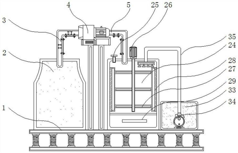
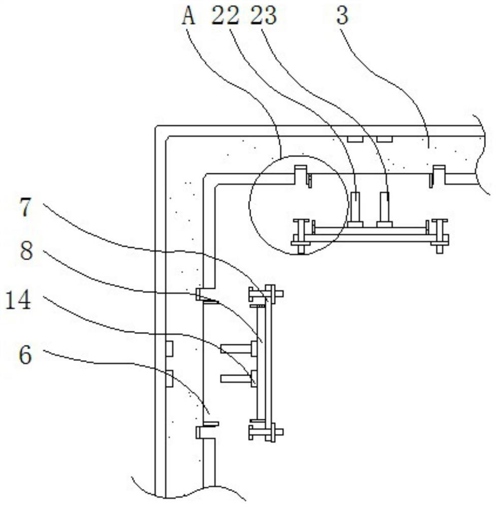
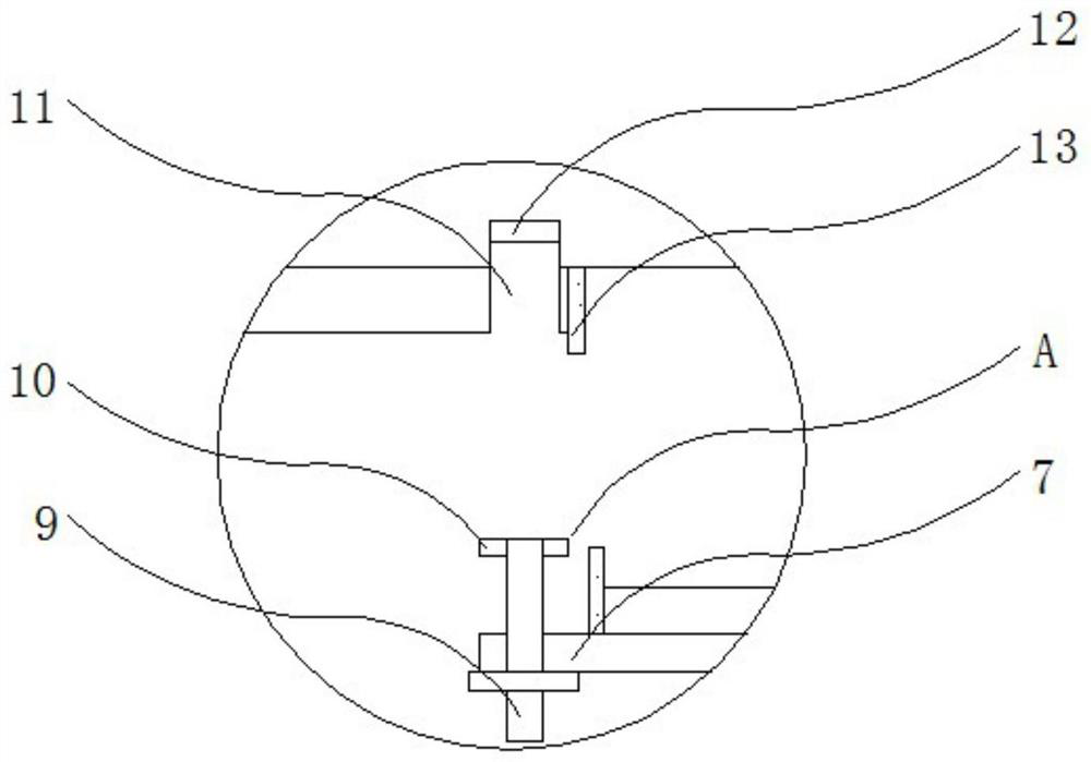
[0031] see Figure 1-8, the present invention provides a technical solution: a desulfurization and denitrification purification device for industrial boiler flue gas separation for coal power plants, including a load-bearing base 1, an industrial boiler body 2, an air outlet pipe 3, an exhaust fan 4, an air inlet pipe 5, and an installation port 6. Dustproof cover 7, end strip 8, threaded rod 9, lock block 10, connection groove 11, lock groove 12, gasket 13,...


PUM


Abstract

The invention discloses a desulfurization and denitrification purification device for separating industrial boiler flue gas used in a coal power plant, which comprises a load-bearing base, an installation port, a connecting sleeve and a desulfurization and denitrification tower. The upper end of the load-bearing base is equipped with an industrial boiler body. The inner wall of the connecting sleeve is provided with a connecting rod, the input end of the desulfurization and denitrification tower is seamlessly connected with the output end of the intake pipe, and an ammonia gas inlet is opened on the left side of the top of the desulfurization and denitrification tower, and the ammonia gas enters A drive motor is installed on the right side of the gas port, a water tank is installed on the right side of the desulfurization and denitrification tower, and a water pump is installed inside the water tank. In the desulfurization and denitrification purification device for separation of industrial boiler flue gas used in coal power plants, the outlet pipe and the dust cover, as well as the inlet pipe and the dust cover are connected by slots, which is convenient for the user to adjust the connection between the outlet pipe and the dust cover. The disassembly and assembly between the air inlet pipe and the dust cover is convenient for the user to dredge and clean the inside of the air outlet pipe and the air inlet pipe, so as to ensure the working efficiency of the air outlet pipe and the air inlet pipe.

Description

technical field [0001] The invention relates to the related technical field of boiler flue gas treatment, in particular to a desulfurization and denitrification purification device for separation of industrial boiler flue gas used in coal power plants. Background technique [0002] A coal power plant is a factory that uses coal to produce electricity. Its basic production process is that when coal is burned, water is heated to generate steam, which converts the chemical energy of the coal into heat energy. The steam pressure drives the steam turbine to rotate, and the heat energy is converted into mechanical energy, and then the steam turbine drives power generation. The machine rotates to convert mechanical energy into electrical energy. Therefore, a boiler is used in the process of coal combustion. The boiler also produces flue gas during the working process, and the dust contained in the flue gas includes fly ash, carbon black, sulfur and nitrogen. The oxides are all subs...

Claims


Application Information

Patent Timeline
Patent Type & Authority Patents(China)
IPC IPC(8): B01D53/76B01D53/60B01D46/12B01D46/00B08B9/087B08B9/093
CPCB01D46/12B01D53/60B01D53/76B08B9/087B08B9/093B01D2258/0283B01D46/62Y02A50/2351
Inventor 蒙建敏
Owner 江苏绿叶环境工程集团有限公司
Why Eureka
Try Eureka