Tooling for pipe processing

A pipeline and tooling technology, applied in the field of welding pipeline flange tooling, can solve the problems of reducing work efficiency, slipping on the ground, smashing and other problems, and achieving the effect of preventing personal injury

Active Publication Date: 2020-11-10
徐州致锦智能设备有限公司
View PDF9 Cites 0 Cited by
  • Summary
  • Abstract
  • Description
  • Claims
  • Application Information

AI Technical Summary

Problems solved by technology

[0002] In the process of welding flanges to pipes, it is necessary to manually move the pipes to the support wheels, and after welding, it is still necessary to manually remove the shelves. smashed
[0003] At present, there is a model that can move the pipeline to the supporting wheel without manpower. A push rod is arranged on the front end side of the pipe placement frame through a rotating shaft, and a baffle is arranged at the rear end of the pushing rod; Rod, after the ejector rod falls on the gear rod, the baffle is higher than the pipe placement frame; but when this kind of tooling transports the pipe to the support frame, it is necessary to lift the front end of the ejector rod by hand, and the rear end of the baffle falls , the pipe rolls over the top of the baffle and falls from the pipe placement frame to the support wheel; and after the flange is welded, the pipe still needs to be transported to the slide frame, and the pipe is transported to the parallel frame through the slide frame, and the pipe is transported During the process, if the pipeline is not horizontal, it is easy to slip on the ground
[0004] At present, there is no tool that can transfer the pipe to the support wheel without manual operation and can also correct the welding pipe flange that appears tilted when the pipe is conveyed on the slide frame. With the development of technology, we have designed a Tooling for pipe processing that can correct the inclination of pipes without manual work

Method used


Image

  • Tooling for pipe processing
  • Tooling for pipe processing
  • Tooling for pipe processing

Examples


Embodiment Construction

[0040] In order to better understand the present invention, the embodiments of the present invention will be explained in detail below with reference to the accompanying drawings.

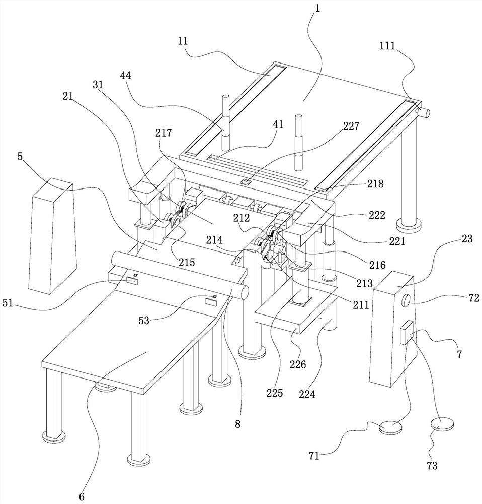
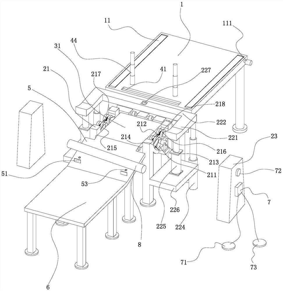
[0041] As attached figure 1 Attached Picture 11 As shown, the present invention includes a pipe placement frame 1, a positioning mechanism 2, a pushing mechanism 3, a blocking mechanism 4, a slide frame 5, a horizontal frame 6 and a controller 7.

[0042] The pipe placing rack 1 is provided with symmetrical strip grooves on the left and right sides, and a conveyor belt 11 is arranged in the strip groove. The two conveyor belts 11 are 0.5-1.5 cm higher than the upper surface of the pipe placing rack 1, preferably The height is 1cm. The front and rear ends of the two conveyor belts 11 are respectively connected by a rotating roller, and one side of the rotating roller is drivingly connected with a driving motor I111; the driving connection may be the motor shaft of the driving motor I111 and the rotatin...


PUM


Abstract

The invention discloses a fixture for pipeline processing. The fixture comprises a pipeline placement frame, a positioning mechanism, a pushing mechanism, a spacer mechanism, a landslide frame, a horizontal frame and a controller, wherein conveyor belts are symmetrically arranged at the left side and right side of the pipeline placement frame; the positioning mechanism is arranged at the front endof the pipeline placement frame; a lifting mechanism is arranged below a pipeline bracket; a sensor I is arranged at the upper end of a connecting rod; operating platforms are arranged at the left side and right side of the positioning mechanism; the spacer mechanism comprises a spacer plate, a spring and a bracing wire; one end of the bracing wire is fixedly connected to a pipeline supporting plate; the other end of the bracing wire bypasses a lead wire wheel, passes through a bracing wire through hole and is connected to the bottom of the spacer plate; the pushing mechanism comprise a pushing plate and a hydraulic cylinder; the pushing plate is in hinge joint with the tail end of the landslide frame; a plurality of correcting plates are arranged at the tail end of the landslide frame ina left and right symmetrical manner; and pushing air cylinders are arranged at the bottoms of the correcting plates. The fixture saves time and labor, has a good safety performance and is convenientand practical.

Description

Technical field [0001] The invention relates to a tooling for welding pipeline flanges, in particular to a tooling for pipeline processing. Background technique [0002] In the process of welding flanges to the pipeline, it is necessary to manually move the pipeline to the support wheel, and after the welding is completed, it is still necessary to manually move the rack down, which not only reduces the work efficiency, but also accidentally gets caught during the transportation process. Smashed. [0003] At present, there is a model that can move the pipeline to the support wheel without human power. A push rod is provided on the front side of the pipeline placement frame through a rotating shaft, and the rear end of the push rod is provided with a baffle; a gear is provided at the front and bottom of the rotating shaft. After the ejector rod falls on the stop rod, the baffle is higher than the pipe placement frame; but when this tooling transports the pipe to the support frame, t...

Claims


Application Information

Patent Timeline
Patent Type & Authority Patents(China)
IPC IPC(8): B23K37/00B23K37/047B24B41/00
CPCB23K37/00B23K37/047B24B41/005
Inventor 刘芳艳
Owner 徐州致锦智能设备有限公司
Why Eureka
Try Eureka