
Convenient-to-use automated winding machine

A winder, a convenient technology, is applied in the cutting of textile materials, textile and papermaking, transportation of filamentous materials, etc., and can solve the problems of reducing the production efficiency of the winder, improving the labor force, and the pulling force of unwinding, etc., Achieve simple structure, improve yarn quality and reduce friction

Pending Publication Date: 2019-02-05
湖州萌星服饰有限公司
View PDF0 Cites 10 Cited by
  • Summary
  • Abstract
  • Description
  • Claims
  • Application Information

AI Technical Summary

Problems solved by technology

When the current winding machine winds the winding reel to a certain diameter, the yarn is usually cut by rewinding workers, which greatly improves the labor force and reduces the production efficiency of the winding machine.
In addition, in the process of processing, there are common problems such as inner looseness and outer tightness, slow speed, and poor forming. The winding will become tighter and tighter. When processing silk products, especially the unwinding of the filament tube, because the length of the filament tube is long during unwinding at high speed, as the diameter gradually becomes smaller, the pulling force of unwinding will become larger and larger, and the finished product The bobbin winding density gradually

Method used

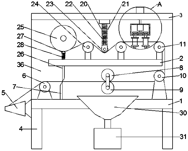
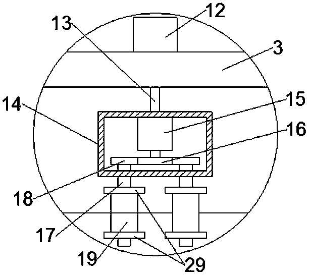
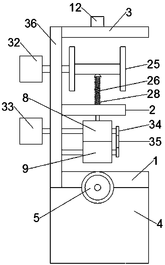

Image

  • Convenient-to-use automated winding machine
  • Convenient-to-use automated winding machine
  • Convenient-to-use automated winding machine

Examples


Embodiment Construction

[0017] The following will clearly and completely describe the technical solutions in the embodiments of the present invention with reference to the accompanying drawings in the embodiments of the present invention. Obviously, the described embodiments are only some, not all, embodiments of the present invention. Based on the embodiments of the present invention, all other embodiments obtained by persons of ordinary skill in the art without making creative efforts belong to the protection scope of the present invention.

[0018] Such as Figure 1-Figure 3 As shown, a convenient automatic winding machine includes a lower plate 1, a middle plate 2, an upper plate 3, a vertical plate 36, a bobbin 5, a fixed cutter 7, a polishing device, a waxing device, and a winding reel Barrel 25, and movable cutter 26. The left and right sides of lower plate 1 bottom are respectively provided with support plate 4, and the top rear side of lower plate 1 is fixed with vertical plate 36, and the ...


PUM


Abstract

The invention discloses a convenient- to-use automated winding machine. The winding machine comprises a lower plate, a middle plate, an upper plate, a vertical plate, a yarn twisting cylinder, a fixedcutting blade, a grinding device, a waxing device, a yarn coiling reel and a movable cutting blade. Supporting plates are arranged on the left side and the right side of the bottom of the lower platerespectively. The vertical plate is fixed to the rear side above the lower plate. The middle plate parallel with the lower plate is arranged in a middle position of the vertical plate. The upper plate parallel with the middle plate is arranged on the top of the vertical plate. The yarn twisting cylinder is arranged on a side face of the supporting plate on the left side below the lower plate. A first guide pulley is arranged on the upper left side of the lower plate. The fixed cutting blade is arranged on the right side of the first guide pulley. A second guide pulley is arranged on the upperright side of the lower plate. The grinding device is arranged between the first guide pulley and the second guide pulley. According to the convenient- to-use automated winding machine, the structureis simple; flaws on the yarn can be eliminated in an automated manner; and yarn quality is improved.

Description

technical field [0001] The invention relates to the technical field of textile equipment, in particular to a convenient automatic winder. Background technique [0002] The winding machine is a special equipment for the textile industry. The main task of the winding machine is to wind the yarn on the winding drum of the winding machine, remove the defects on the yarn, and improve the quality of the yarn. When the current winding machine winds the winding reel to a certain diameter, the yarn is usually cut by rewinding workers, which greatly improves the labor force and reduces the production efficiency of the winding machine. In addition, in the process of processing, there are common problems such as inner looseness and outer tightness, slow speed, and poor forming. The winding will become tighter and tighter. When processing silk products, especially the unwinding of the filament tube, because the length of the filament tube is long during unwinding at high speed, as the ...

Claims


Application Information

Patent Timeline
Patent Type & Authority Applications(China)
IPC IPC(8): B65H54/70B65H59/10B65H71/00B65H57/14D06H7/00
CPCD06H7/00B65H54/702B65H57/14B65H59/10B65H71/002B65H71/005B65H2701/31
Inventor 王图星
Owner 湖州萌星服饰有限公司
Learn More