
Gas tightness detector easy to be observed for production and detection of engine

A technology for the production of testing and measuring instruments, which is applied in the direction of liquid tightness measurement using liquid/vacuum degree, and detecting the appearance of fluid at the leakage point, etc., can solve the problems of single phenomenon structure, single function, single observation structure, etc., to achieve Removal and installation operations save labor, improve accuracy, and reduce operational difficulty

Active Publication Date: 2019-02-01
ANHUI ANKAI AUTOMOBILE
View PDF7 Cites 2 Cited by
  • Summary
  • Abstract
  • Description
  • Claims
  • Application Information

AI Technical Summary

Problems solved by technology

[0003] The existing airtightness tester equipment has certain disadvantages in the process of use. The traditional airtightness tester observes the internal pressure change of the airtightness tester through the gas sensor, and only has a single observation structure. When the traditional gas sensor fails, use The operator cannot use the airtightness tester to obtain accurate test results, the phenomenon structure is relatively simple, the traditional airtightness tester is an integrated structure, and the engine parts themselves have a certain weight. The repeated moving operation of the engine parts increases the difficulty of the user's operation, and the removal operation of the detection parts is laborious. The traditional seal tester adopts a screw-fixed structure, which reduces the sealability of the seal tester. The sealing structure is relatively simple and the functions are relatively Single, bring certain adverse effects to users

Method used


Image

  • Gas tightness detector easy to be observed for production and detection of engine
  • Gas tightness detector easy to be observed for production and detection of engine
  • Gas tightness detector easy to be observed for production and detection of engine

Examples


Embodiment Construction

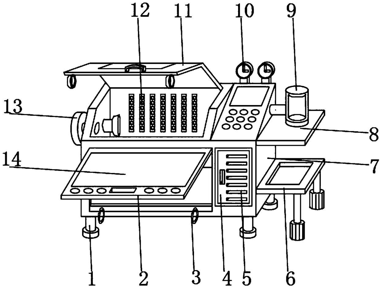
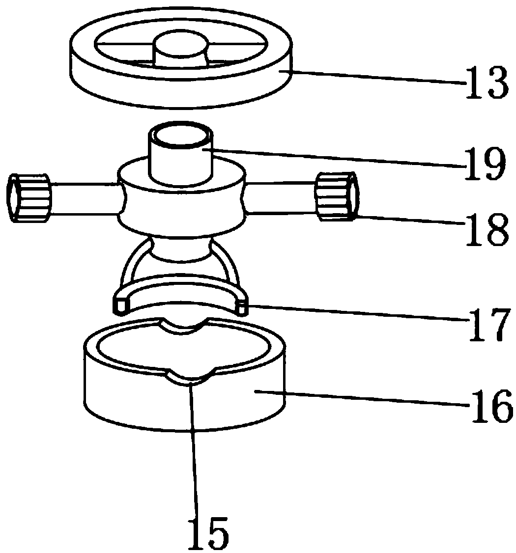
[0028] The technical solutions in the embodiments of the present invention will be clearly and completely described below in conjunction with the embodiments of the present invention. Apparently, the described embodiments are only some of the embodiments of the present invention, not all of them. Based on the embodiments of the present invention, all other embodiments obtained by persons of ordinary skill in the art without creative efforts fall within the protection scope of the present invention.

[0029] like Figure 1-5 As shown, an airtightness measuring instrument for engine production inspection that is convenient for observation includes a protective shell 7, a communication seat 19 and a sliding draw plate 21, and the front outer surface of the protective shell 7 is movably equipped with a side pull flip cover 2, and The outer surface of the upper end of the side pull flip cover 2 is fixedly equipped with an observation window 14, and the outer surface of the front en...


PUM


Abstract

The invention discloses a gas tightness detector easy to be observed for production and detection of an engine, which comprises a protective casing, a communication fixing seat, and a slidable drawingplate. The front outer surface of the protective casing is movably mounted with a side pulling cover. The outer surface of the upper end of the side pulling cover is fixedly mounted with an observingwindow. The front outer surface, near the lower portion of the side pulling cover, of the protective casing is fixedly mounted with two sets of fixing pull rings. The non-slip legs are fixedly mounted at four corners of the outer surface of the lower end of the protective casing. A side of the front outer surface, near the observing window, of the protective casing is fixedly mounted with a fixedshutter. Six sets of ventilation slots are equally spaced on the inside of the front portion of the fixed shutter. The gas tightness detector easy to be observed for the production and detection of the engine can make the gas tightness detector has multiple imaging structures, improves measuring precision, avoids misjudgment, saves the labor of the installation and removal operation of measuringcomponents, and improves the sealing performance of a device.

Description

technical field [0001] The invention belongs to the technical field of engine production, and in particular relates to an air tightness detector, in particular to an easy-to-observe air tightness measuring instrument for engine production and detection. Background technique [0002] The leak tester is connected to a test chamber, specially designed to hold the package to be tested. The test chamber package is placed in the test chamber to be evacuated. Single or dual gas sensor technology is used to monitor the test chamber as two levels. The vacuum state also monitors the vacuum changes during the predetermined test period. The changes of absolute vacuum and relative vacuum imply the leakage and defects in the packaging. Special testing equipment, using tightness measuring instruments to monitor the airtightness of the produced engine parts, so as to improve the qualified rate of engine parts production; [0003] The existing airtightness tester equipment has certain disad...

Claims


Application Information

Patent Timeline
Patent Type & Authority Applications(China)
IPC IPC(8): G01M3/20
CPCG01M3/20
Inventor 董作磊詹桉李佳李海郭培忠
Owner ANHUI ANKAI AUTOMOBILE
Learn More