A dryer suitable for ceramic pipes

A technology for ceramic pipes and dryers, applied in dryers, ceramic products drying, drying and other directions, can solve the problems affecting the overall energy consumption of ceramic enterprises, low ceramic drying efficiency, long ceramic drying time, etc. Drying effect and drying efficiency, improving drying effect and saving manufacturing cost

Active Publication Date: 2020-09-25
三门县点帆环保科技有限公司
View PDF8 Cites 0 Cited by
  • Summary
  • Abstract
  • Description
  • Claims
  • Application Information

AI Technical Summary

Problems solved by technology

Although drying is a relatively simple technology, it is widely used in industrial processes. It not only affects the quality and yield of ceramic products, but also affects the overall energy consumption of ceramic enterprises.
In the prior art, the drying device for ceramic pipes has the problem of high energy consumption due to the long drying time of ceramics, and the drying efficiency of ceramics is low and the drying is uneven.

Method used


Image

  • A dryer suitable for ceramic pipes
  • A dryer suitable for ceramic pipes
  • A dryer suitable for ceramic pipes

Examples


specific Embodiment approach 1

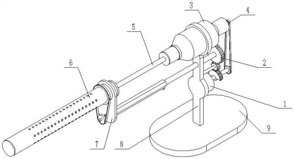
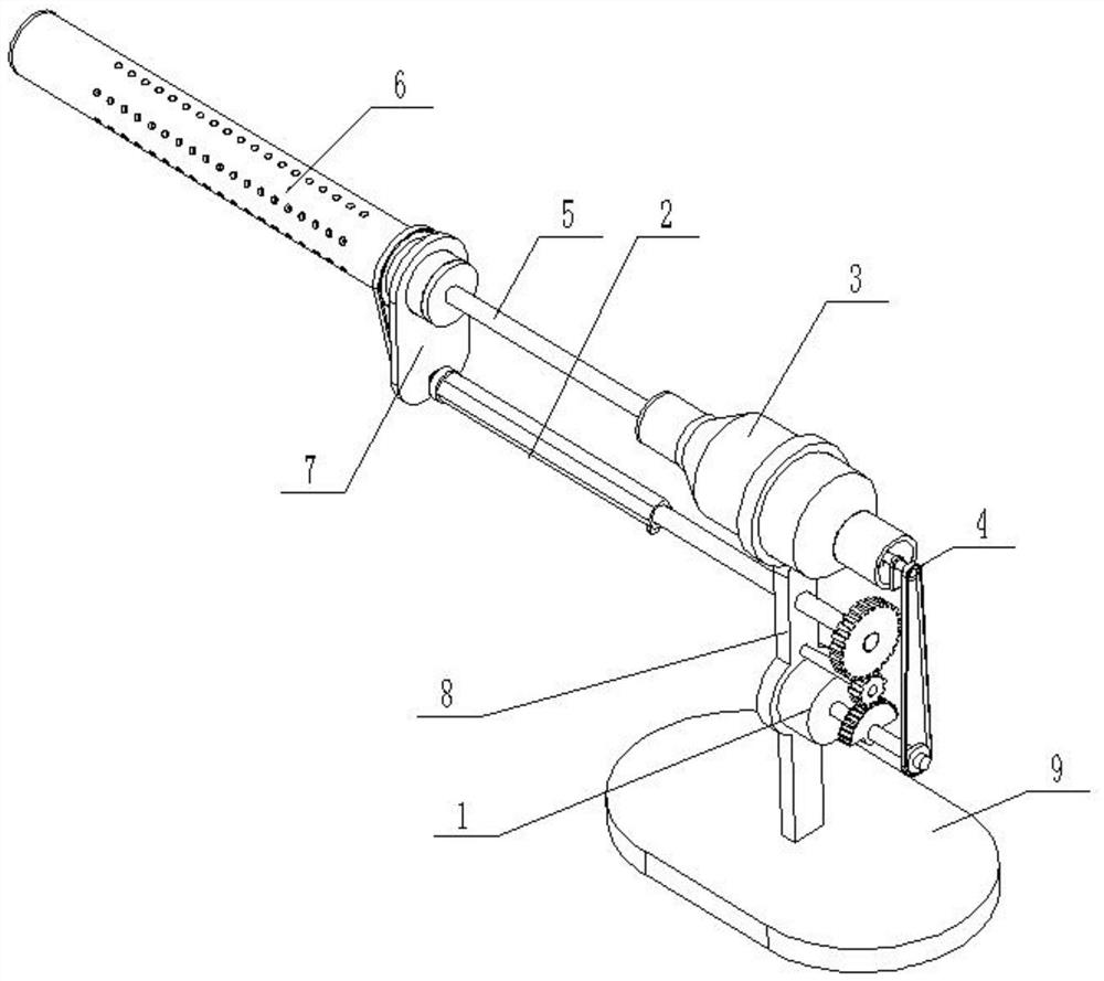
[0041] like Figure 1-13As shown, a dryer suitable for ceramic pipes includes a driving device 1, a transmission wheel 2, a ventilator 3, an exhaust fan 4, an air guide pipe 5, a rotating air pipe 6, a movable frame plate 7, and a vertical frame plate 8 And base plate 9, described driving device 1 comprises servomotor 1-1, drive shaft 1-2, half gear 1-3, reduction gear 1-4, axle 1-5 and driving pulley 1-6; The motor 1-1 is fixedly connected to the vertical frame plate 8 through the motor base, and the vertical frame plate 8 is fixedly connected to the base plate 9; the output shaft of the servo motor 1-1 is connected to the drive shaft 1-2 through a coupling; Said driving shaft 1-2 is fixedly connected with half gear 1-3 and driving pulley 1-6, and the axes of driving shaft 1-2, half gear 1-3 and driving pulley 1-6 are collinear; said half gear 1 -3 meshing transmission connection reduction gear 1-4, reduction gear 1-4 is fixedly connected on the wheel shaft 1-5, the axes of ...

specific Embodiment approach 2

[0044] Such as Figure 1-13 As shown, the transmission wheel 2 includes a linkage gear 2-1, a rotating shaft 2-2, a limit slider 2-3, a rotating sleeve 2-4, a stepped shaft 2-5 and a first pulley 2-6; the rotating shaft 2-2. The axes of the rotating sleeve 2-4, the stepped shaft 2-5 and the first pulley 2-6 are collinear, and the linkage gear 2-1 meshes with the reduction gear 1-4; the linkage gear 2 -1 is fixed on one end of the rotating shaft 2-2, the rotating shaft 2-2 is rotatably connected to the vertical frame plate 8 through a bearing with a seat and is provided with axial positioning, and the other end of the rotating shaft 2-2 is slidingly fitted and connected to the rotating sleeve 2- 4. The inner side of one end is provided with a horizontal chute 2-4-1 on the pipe surface of the rotating sleeve 2-4, and the limit slider 2-3 is slidably connected to the inside of the horizontal chute 2-4-1, and the limit slide The block 2-3 is fixedly connected to the rotating shaf...

specific Embodiment approach 3

[0047] Such as Figure 1-13 As shown, two axial retaining rings 2-5-1 are threadedly connected to the stepped shaft 2-5, and the two axial retaining rings 2-5-1 are arranged at both ends of the vertical frame plate 8 respectively. The arrangement of the axial stop ring 2-5-1 on the stepped shaft 2-5 can prevent the stepped shaft 2-5 from being separated from the movable frame plate 7, and play a role of limiting and positioning the stepped shaft 2-5.


PUM


Abstract

The invention relates to the field of ceramic pipeline processing, in particular to a dryer suitable for a ceramic pipeline. The dryer suitable for the ceramic pipeline comprises a driving device, a driving wheel, a ventilator, a pump drainage fan, an air guiding pipe, a rotary air pipe, a movable frame plate, a vertical frame plate and a base plate, wherein the driving device comprises a servo motor, a drive shaft, a half gear, a reduction gear, a wheel shaft and a driving pulley; the servo motor is fixedly connected onto the vertical frame plate through a motor base; the vertical frame plateis fixedly connected onto the base plate; an output shaft of the servo motor is connected with the drive shaft through a coupler; the half gear and the driving pulley are fixedly connected onto the drive shaft; the half gear is connected with the reduction gear in a meshing way; the reduction gear is fixedly connected onto the wheel shaft; and the wheel shaft is connected onto the vertical frameplate in a running fit way. The dryer suitable for the ceramic pipeline provided by the invention can be inserted into the ceramic pipeline so as to dry and dehumidify the ceramic pipeline, and high agood drying effect, high drying efficiency and low energy consumption.

Description

technical field [0001] The invention relates to the field of processing ceramic pipes, in particular to a dryer suitable for ceramic pipes. Background technique [0002] Ceramics are various products made of natural clay and various natural minerals as the main raw materials through crushing, kneading, molding and calcination. The drying of ceramics is one of the very important processes in the production process of ceramics. Most of the quality defects of ceramic products are caused by improper drying. [0003] The drying of the ceramic industry has experienced natural drying, chamber drying, and now continuous dryers with various heat sources, far-infrared dryers, solar dryers and microwave drying technologies. Although drying is a relatively simple technology, it is widely used in industrial processes. It not only affects the quality and yield of ceramic products, but also affects the overall energy consumption of ceramic enterprises. The drying device for ceramic pipes...

Claims


Application Information

Patent Timeline
Patent Type & Authority Patents(China)
IPC IPC(8): F26B21/00F26B25/00F26B25/02
CPCF26B21/001F26B21/003F26B21/004F26B25/00F26B25/02F26B2210/02
Inventor 李海源
Owner 三门县点帆环保科技有限公司
Why Eureka
Try Eureka