Thermal image monitoring head based on wireless infrared rays

A monitoring head and infrared technology, which is applied in the field of monitoring head and thermal image monitoring head, can solve the problems of falling danger, poor monitoring effect, poor firmness, etc., and achieve the effect of prolonging service life, reasonable design, and accelerating heat dissipation

Inactive Publication Date: 2019-02-01
ZHENGZHOU HAIWEI OPTOELECTRONICS TECH CO LTD
View PDF10 Cites 0 Cited by
  • Summary
  • Abstract
  • Description
  • Claims
  • Application Information

AI Technical Summary

Problems solved by technology

[0003] There are many deficiencies in existing thermal imaging monitoring heads. First, the installation of the monitoring head is not easy to adjust, so there are often large blind spots when monitoring, resulting in poor monitoring effect. Dust adheres to the outer surface of the lens, so that the reflected infrared light changes direction after being refracted by the dust, thus blurring the video and affecting the clarity of the monitoring picture. Third, the thermal image monitoring head will generate heat when it is working. If the heat dissipation cannot be carried out in time, it will affect the service life of the internal components. Fourth, when installing the thermal image monitoring head, it is more likely to use paste or hooks to connect with the wall, which has poor firmness and exists certain fall hazard

Method used


Image

  • Thermal image monitoring head based on wireless infrared rays
  • Thermal image monitoring head based on wireless infrared rays
  • Thermal image monitoring head based on wireless infrared rays

Examples


Embodiment Construction

[0017] The following will clearly and completely describe the technical solutions in the embodiments of the present invention with reference to the accompanying drawings in the embodiments of the present invention. Obviously, the described embodiments are only some, not all, embodiments of the present invention. Based on the embodiments of the present invention, all other embodiments obtained by persons of ordinary skill in the art without making creative efforts belong to the protection scope of the present invention.

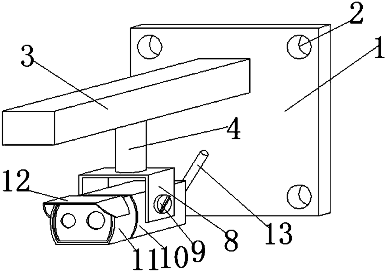
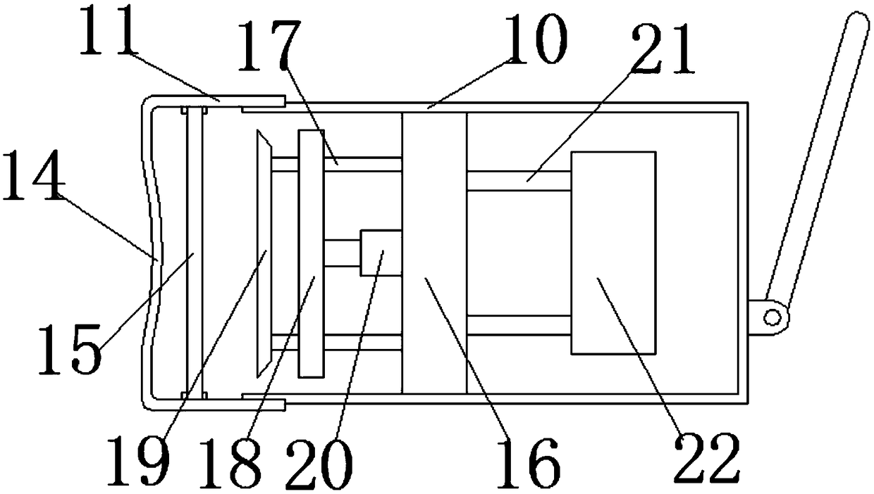
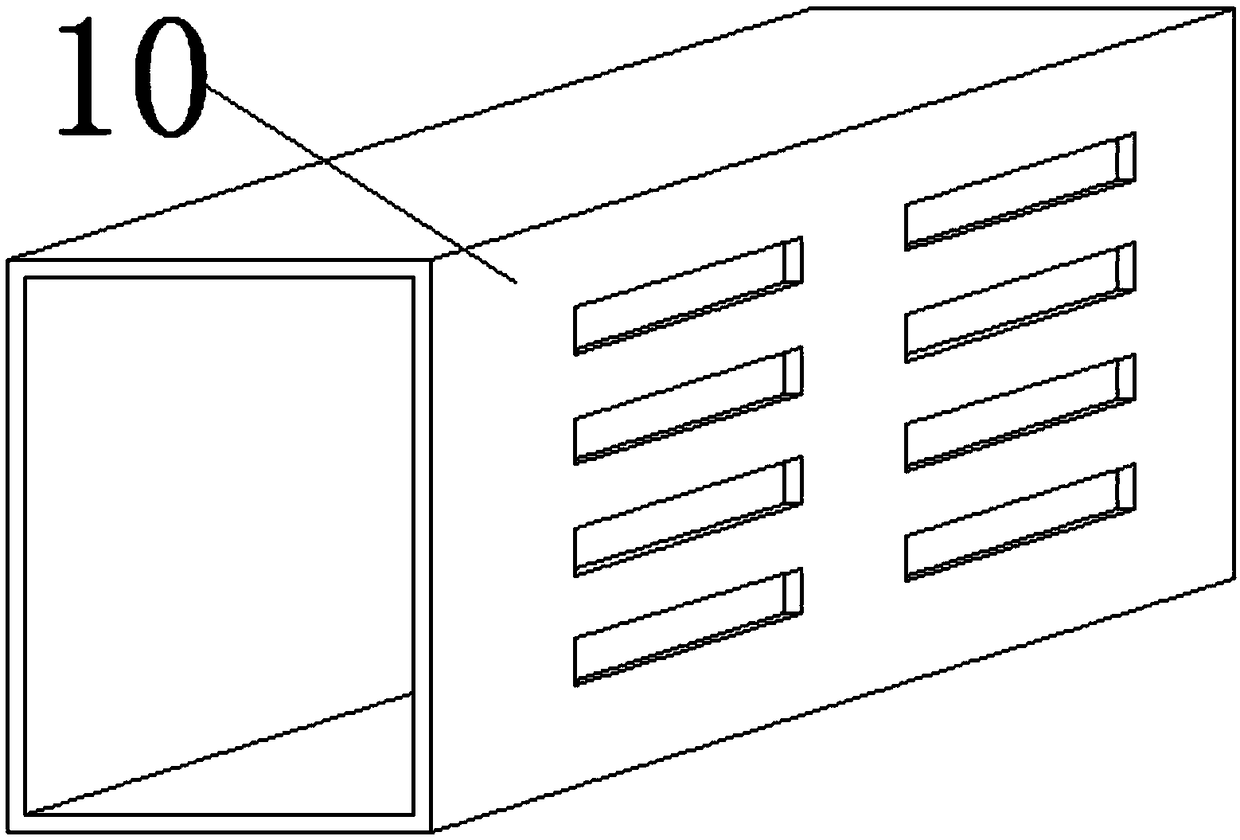
[0018] see Figure 1~4 , a thermal image monitoring head based on wireless infrared, including a mounting base plate 1, mounting holes 2, supporting cross bars 3, connecting shafts 4, chute 5, sliders 6, fastening nuts 7, U-shaped connecting plates 8, fixing Bolt 9, rear shell 10, front cover 11, dust shield 12, WIFI antenna 13, circular through hole 14, optical filter 15, connection base 16, support ring 17, hot spot element 18, lens 19, infrared lamp 20 , p...


PUM


Abstract

The invention discloses a thermal image monitoring head based on wireless infrared rays. The thermal image monitoring head comprises a mounting base plate, a mounting hole, a supporting cross rod, a connecting shaft, a sliding groove, a sliding block, a fastening nut, an U-shaped connecting plate, fixing bolts, a rear shell, a front cover, a dust board, a WIFI antenna, a circular through hole, a light filter, a connecting base, a supporting ring, a hot spot element, a lens, an infrared lamp, a pin and an information processing chip; the fixing bolts are located on the two sides of the rear shell; the rear shell is in rotating connection with the U-shaped connecting plate through the fixing blots, so that the tilting angle of a monitoring head is adjusted conveniently; the dust board protrudes out of the front edge of the front cover, so that the phenomenon that dust is adhered to the circular through hole of the front cover to affect monitoring is avoided; a plurality of cooling grooves are evenly distributed in the bottom of the rear shell, so that cooling is accelerated; the input end of the information processing chip is electrically connected with the hot spot element through apin; and the output end of the information processing chip is electrically connected with the WIFI antenna through a guide wire so that monitored images can be transmitted to a mobile terminal.

Description

technical field [0001] The invention relates to a monitoring head, in particular to a thermal image monitoring head based on wireless infrared, and belongs to the technical field of infrared camera monitoring. Background technique [0002] Infrared thermal imaging is a kind of infrared radiation used to detect target objects, and through photoelectric conversion, electrical signal processing and other means, the temperature distribution image of the target object is converted into a video image, which can be monitored 24 hours a day and night. It is better, the irradiation distance is far, the picture quality is fine and clear, and the service life is longer than ordinary ones. [0003] There are many deficiencies in existing thermal imaging monitoring heads. First, the installation of the monitoring head is not easy to adjust, so there are often large blind spots when monitoring, resulting in poor monitoring effect. Dust adheres to the outer surface of the lens, so that th...

Claims


Application Information

Patent Timeline
Patent Type & Authority Applications(China)
IPC IPC(8): F16M13/02F16M11/06G01J5/00
CPCF16M11/06F16M13/02G01J5/00G01J2005/0077G01J5/485
Inventor 焦战威
Owner ZHENGZHOU HAIWEI OPTOELECTRONICS TECH CO LTD
Why Eureka
Try Eureka