
Battery energy storage system

A technology for battery energy storage systems and battery racks, which is applied in secondary batteries, battery load switching, battery pack components, etc., and can solve problems affecting battery pack consistency, service life, wiring, inconvenient maintenance, and different currents, etc. , to achieve the effect of reducing labor cost, reducing circuit length and reducing short circuit

Active Publication Date: 2019-01-29
SHENZHEN CLOU ELECTRONICS
View PDF9 Cites 6 Cited by
  • Summary
  • Abstract
  • Description
  • Claims
  • Application Information

AI Technical Summary

Problems solved by technology

In the prior art, the battery packs are connected in series with power cables, and then the total positive and negative poles of the battery clusters are respectively converged to the positive pole and negative pole of the busbar of the DC confluence cabinet by cables, which consumes a lot of manpower. In the processing and production of each power cable, there will be artificial differences in the crimping process of each power cable. Due to the connection position and distance of the power cable, the length of the cable from each cluster to the busbar will also be different. On the whole, each cluster The length and internal resistance of the circuit to the busbar will be different, resulting in different currents allocated to each cluster, which will affect the consistency and service life of each cluster of battery packs
In addition, if the power cable is used, the positive and negative cables are generally outgoing at the same time, which is inconvenient for wiring and maintenance, and is easy to short circuit, causing fire or electric shock accidents.

Method used


Image

  • Battery energy storage system
  • Battery energy storage system
  • Battery energy storage system

Examples


Embodiment Construction

[0025] In order to make the object, technical solution and advantages of the present invention clearer, the present invention will be further described in detail below in conjunction with the accompanying drawings and specific embodiments. It should be understood that the specific embodiments described here are only used to explain the present invention, not to limit the present invention.

[0026] In the following text, many aspects of the invention will be better understood with reference to the accompanying drawings. Components in the figures are not necessarily drawn to scale. Instead, emphasis is placed on clearly illustrating the components of the invention. Furthermore, like reference numerals indicate corresponding parts throughout the several views of the drawings.

[0027] As used herein, the word "exemplary" or "illustrative" means serving as an example, instance, or illustration. Any implementation described herein as "exemplary" or "illustrative" is not necessa...


PUM


Abstract

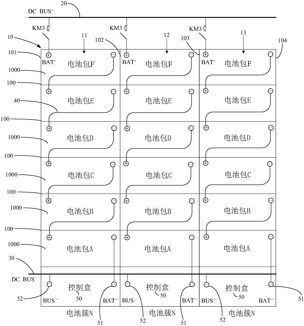
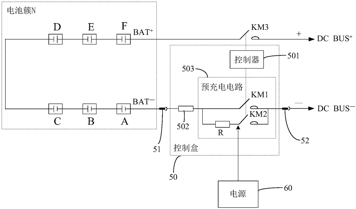
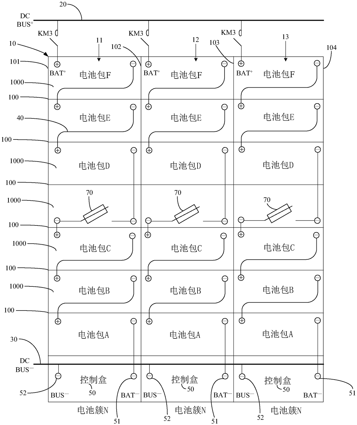
The invention relates to the technical filed of energy storage batteries, in particular to a battery energy storage system. The battery energy storage system comprises a battery rack module, a direct-current conflux positive bus row, a direct-current conflux negative bus row and multiple battery clusters. According to the battery energy storage system, on one hand, soft copper rows are adopted forreplacing traditional power cables in power loop connection among battery packs, the labor cost can be effectively reduced, the circuit length difference and internal resistance difference of the battery clusters are reduced, current equalization of the battery clusters is guaranteed, the consistency of electrical performance is good, accordingly, the energy efficiency of the battery clusters isimproved, and the service life of the battery clusters is prolonged; on the other hand, the direct-current conflux positive bus row and the direct-current conflux negative bus row are arranged on thetwo sides of the battery rack module respectively at intervals, the situation is avoided that line outgoing exists at the total positive output ends and total negative output ends of the battery clusters simultaneously, wire arrangement and maintenance are convenient, meanwhile, the safe distance between a positive pole and a negative pole is guaranteed, and accordingly the risks of short circuitsand electric leakage are effectively reduced.

Description

technical field [0001] The invention relates to the technical field of energy storage batteries, in particular to a battery energy storage system. Background technique [0002] The energy storage system can realize all-round monitoring and energy scheduling management of the working status of the energy storage power station; the battery pack is a battery pack composed of multiple cells connected in series and parallel; the battery cluster is composed of battery packs connected in series and parallel battery array. In the energy storage system, the battery stack contains multiple rows of battery clusters, and the electric energy charges and discharges the battery through the grid and the energy storage inverter PCS. During the charging and discharging process of the battery, since the circuit length and internal resistance of each cluster to the busbar are inconsistent, according to Ohm's law I=U / R (I is the current, U is the voltage , R is the resistance), so the current ...

Claims


Application Information

Patent Timeline
Patent Type & Authority Applications(China)
IPC IPC(8): H01M10/42H01M2/10H02J7/00H01M50/20H01M50/247
CPCH01M10/425H02J7/0068H01M2010/4271H01M50/20Y02E60/10
Inventor 刘万锦郭鹏亮石桥李光立
Owner SHENZHEN CLOU ELECTRONICS
Learn More