
A parallel igbt power unit

A power unit, parallel technology, applied in the direction of output power conversion devices, electrical components, etc., can solve problems such as uneven current, and achieve the effect of solving uneven current.

Active Publication Date: 2016-02-24
河南许继电力电子有限公司 +2
View PDF4 Cites 0 Cited by
  • Summary
  • Abstract
  • Description
  • Claims
  • Application Information

AI Technical Summary

Problems solved by technology

[0006] The purpose of the present invention is to provide a parallel IGBT power unit to solve the uneven current problem generated when the IGBTs are connected in parallel

Method used


Image

  • A parallel igbt power unit
  • A parallel igbt power unit
  • A parallel igbt power unit

Examples


Embodiment Construction

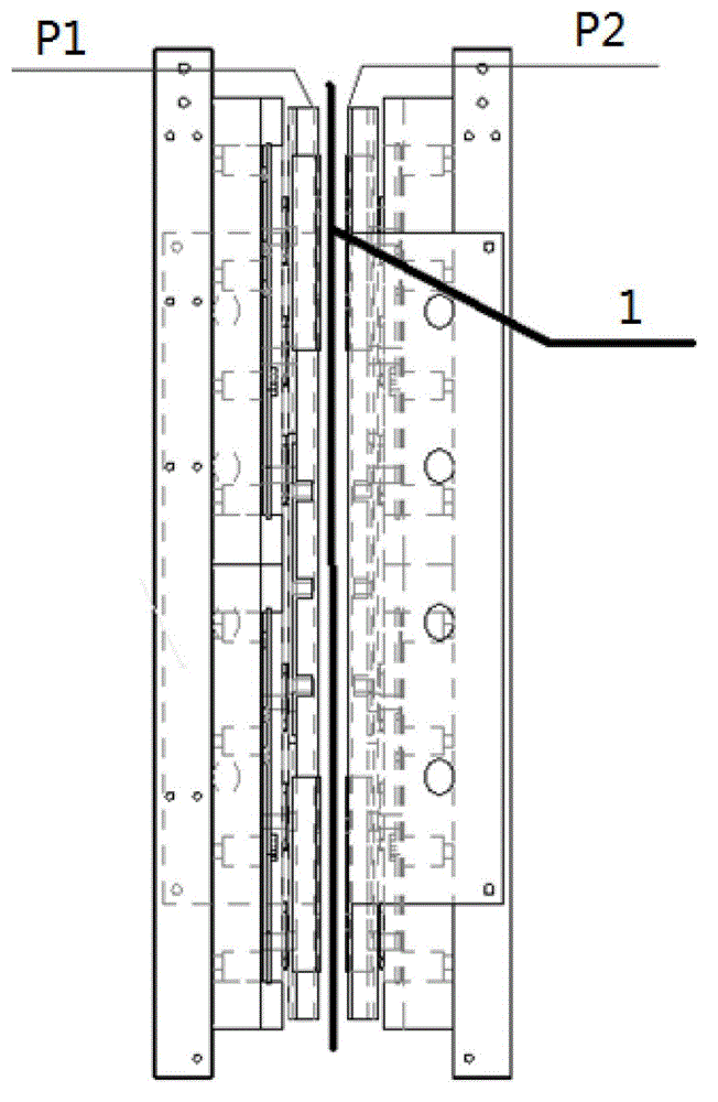
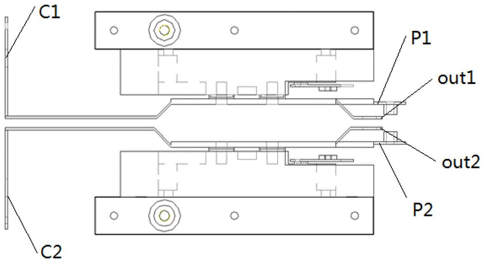
[0027] Such as figure 1 Shown is the electrical structure diagram of the embodiment of the parallel IGBT power unit of the present invention. In this embodiment, each IGBT module includes two parallel IGBT modules for illustration. It can be seen from the figure that the power unit includes two IGBT modules And two busbars with the same structure and symmetrical up and down corresponding to each module, the two busbars are the upper busbar P1 and the lower busbar P2, each IGBT module includes two parallel IGBT modules, this implementation In the example, S1 and S2 are placed on the upper busbar, and S3 and S4 are placed on the lower busbar. The two busbars adopt a laminated design structure, and the two busbars are pressed together through an insulating partition 1 (such as figure 2 shown); from the law of electromagnetic induction, it can be seen that the intensity of magnetic field interference is proportional to the area surrounded by conductors, when the positive and nega...


PUM


Abstract

The invention discloses a parallel IGBT power unit. The parallel IGBT power unit comprises an upper bridge IGBT module and a lower bridge IGBT module. Each IGBT module includes at least two IGBT modules which are connected in parallel, and further comprises an upper busbar and a lower busbar which are correspondingly connected with the two IGBT modules. The upper busbar is provided with a first leading-out terminal for connecting with a first main busbar and a first capacitor connecting terminal for connecting with a capacitor. The lower busbar is provided with a second leading-out terminal for connecting with a second main busbar and a second capacitor connecting terminal for connecting with a capacitor. According to the parallel IGBT power unit, the two IGBT modules and the two busbars which have identical structures and are correspondingly connected with the modules respectively are adopted; the leading-out terminals for connecting with the main busbars and the capacitor connecting terminals for connecting with the capacitors on the busbars are in conductive connection with docking connecting terminals and capacitor connecting terminals at corresponding positions of the IGBT modules of corresponding busbars by using copper bars in identical lengths; and since busbars connecting the IGBTs are identical in length, the current-sharing performance of the parallel IGBT modules on the busbars is guaranteed, and a problem of uneven current during parallel connection of the IGBTs is solved.

Description

technical field [0001] The invention belongs to the application field of power semiconductor components, such as flexible DC transmission, SVG and other high-power power electronic rectification and inverter devices, and specifically relates to a parallel IGBT power unit. Background technique [0002] With the gradual application of flexible direct current transmission (VSC-HVDC) technology in power systems, the reliability of its core component, the high-power insulated gate bipolar transistor (IGBT) valve, has become one of the key factors for power system safety. Because VSC-HVDC devices generally have the characteristics of high voltage, high current, and large capacity, it is difficult to construct a full-load circuit with the same operating conditions as the actual operating conditions in the test environment for testing. Therefore, how to construct an equivalent test circuit in the test environment and conduct a test that is equivalent to the actual operating conditio...

Claims


Application Information

Patent Timeline
Patent Type & Authority Patents(China)
IPC IPC(8): H02M1/00H02M1/44
Inventor 姚为正安昱刘刚孙健夏克鹏孟向军李海鲲
Owner 河南许继电力电子有限公司
Learn More