
Test system for failure spatiotemporal evolution of rock in deep complex environment

A technology for complex environments and test systems, applied in measurement devices, instruments, scientific instruments, etc., can solve problems such as signal inaccuracy and acoustic emission signal interference, and achieve the effect of avoiding interference, avoiding disturbance, and improving test efficiency.

Pending Publication Date: 2019-01-29
SICHUAN UNIV
View PDF5 Cites 5 Cited by
  • Summary
  • Abstract
  • Description
  • Claims
  • Application Information

AI Technical Summary

Problems solved by technology

[0011] The purpose of the present invention is to provide a test system for the temporal and spatial evolution of rock damage in a deep complex environment, to solve the problem of acoustic emission signal interference and signal inconsistencies in the triaxial high temperature, high pressure, seepage and coupling conditions during the rock damage and failure test process under high temperature and high pressure. exact question

Method used


Image

  • Test system for failure spatiotemporal evolution of rock in deep complex environment
  • Test system for failure spatiotemporal evolution of rock in deep complex environment
  • Test system for failure spatiotemporal evolution of rock in deep complex environment

Examples


Embodiment 1

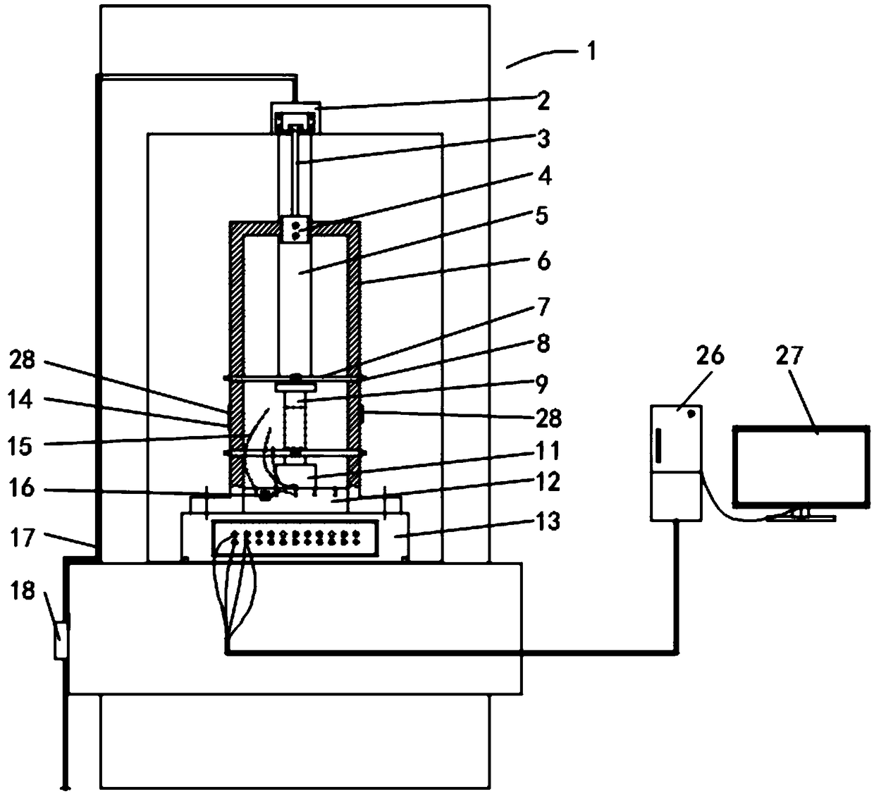
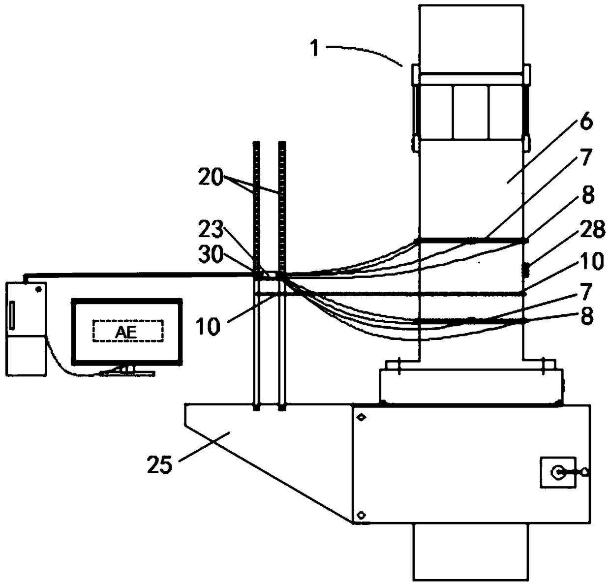
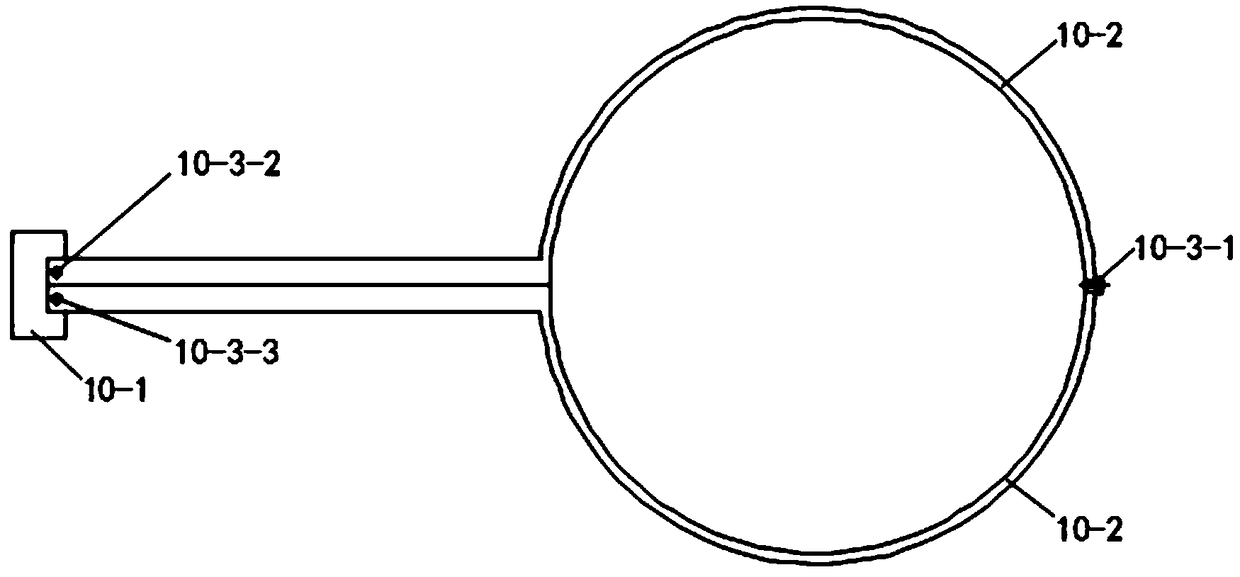
[0056] Such as Figure 1-Figure 18 As shown, the test system for the temporal-spatial evolution of failure in the complex deep rock environment of this embodiment includes an acoustic emission sensor assembly and an acoustic emission amplifier assembly installed on the rock mechanics testing machine 1. The rock mechanics testing machine 1 includes a three-axis Cavity base 13, triaxial chamber 6 installed on the triaxial chamber base 13, triaxial chamber lifting cylinder 2 fixedly installed on the top frame of rock mechanics testing machine 1, the output end of triaxial chamber lifting cylinder 2 is equipped with a lifting rod 3 and the lifting lower end 4 of the lifting rod 3 is fixed on the top of the triaxial cavity 6, and the inner cavity of the triaxial cavity 6 is coaxially installed with a column 5, a test piece indenter 9, and an indenter base 11, and the column 5 is fixed by bolts On the top frame of the rock mechanics testing machine 1, the indenter base 11 is fixed o...

Embodiment 2

[0080] The test system for the spatiotemporal evolution of damage in deep rock complex environments in this embodiment includes an acoustic emission sensor assembly and an acoustic emission amplifier assembly installed on a rock mechanics testing machine 1, and the rock mechanics testing machine 1 includes a three-axis cavity base 13 , the triaxial chamber 6 installed on the triaxial chamber base 13, the triaxial chamber lifting cylinder 2 fixedly installed on the top frame of the rock mechanics testing machine 1, the output end of the triaxial chamber lifting cylinder 2 is installed with a lifting rod 3 and lifted The lifting lower end 4 of the rod 3 is fixed on the top of the triaxial cavity 6, and the inner cavity of the triaxial cavity 6 is coaxially installed with a column 5, a test piece indenter 9, and an indenter base 11 from top to bottom. On the top frame of the testing machine 1, the indenter base 11 is fixed on the three-axis cavity base 13, the space between the te...

Embodiment 3

[0086] The test system for the spatiotemporal evolution of damage in deep rock complex environments in this embodiment includes an acoustic emission sensor assembly and an acoustic emission amplifier assembly installed on a rock mechanics testing machine 1, and the rock mechanics testing machine 1 includes a three-axis cavity base 13 , the triaxial chamber 6 installed on the triaxial chamber base 13, the triaxial chamber lifting cylinder 2 fixedly installed on the top frame of the rock mechanics testing machine 1, the output end of the triaxial chamber lifting cylinder 2 is installed with a lifting rod 3 and lifted The lifting lower end 4 of the rod 3 is fixed on the top of the triaxial cavity 6, and the inner cavity of the triaxial cavity 6 is coaxially installed with a column 5, a test piece indenter 9, and an indenter base 11 from top to bottom. On the top frame of the testing machine 1, the indenter base 11 is fixed on the three-axis cavity base 13, the space between the te...


PUM


Abstract

The invention discloses a test system for failure spatiotemporal evolution of rock in a deep complex environment. The system comprises an acoustic emission sensor assembly and an acoustic emission amplifier assembly which are arranged on a rock mechanical test machine, wherein a three-axis cavity coupling bracket is arranged on the outer wall of a three-axis cavity and between the two acoustic emission sensor assemblies; the three-axis cavity coupling bracket comprises a plate-shaped bracket, two sickle-type brackets and at least three bracket bolts which can be tightly hooped on the outer wall of the three-axis cavity; two guiding columns are vertically fixed on two side faces of the plate-shaped bracket; the acoustic emission amplifier assembly is arranged between the two guiding columnsand above the plate-shaped bracket; and the acoustic emission amplifier assembly is connected to the acoustic emission sensor assembly through a signal line. Through the test system disclosed by theinvention, the problems of acoustic emission signal interference and inaccurate signals occurring under the circumstances of three-axis high temperature, high pressure, seepage and coupling in a rockdamage failure test process under high temperature and high pressure are solved.

Description

technical field [0001] The invention relates to the field of real-time monitoring of rock damage and destruction process under high temperature and high pressure, in particular, it is a test system for the temporal and spatial evolution of rock damage in deep and complex environments. Background technique [0002] The study of rock mechanical properties in the deep environment requires high temperature, high confining pressure triaxial tests, and it is often necessary to couple the rock damage process with acoustic emission in order to conduct a more in-depth analysis of the rock fracture process from an energy perspective. [0003] At present, the acoustic emission test sensor used in the coupled acoustic emission detection test does not have a fixture with good contact, stable contact, and easy displacement, and has the following defects: [0004] A. The design of the existing fixed sleeve of the acoustic emission sensor is unreasonable; the arc-shaped outer wall of the th...

Claims


Application Information

Patent Timeline
Patent Type & Authority Applications(China)
IPC IPC(8): G01N29/14G01N29/22
CPCG01N29/14G01N29/22G01N29/223G01N29/228G01N2291/0232G01N29/227
Inventor 刘建锋张强星雷孝章裴建良邓建辉符文熹徐慧宁薛东杰王璐王春萍廖益林魏进兵陈刚
Owner SICHUAN UNIV
Learn More