Composite multifunctional box bottom structure

A multi-functional and composite technology, applied in the direction of containers, packaging items, special packaging items, etc., can solve the problems of secondary damage to the items in the box, waste of resources, damaged items in the box, etc., to avoid excessive local temperature difference, The effect of preventing items from rotting and solving drainage problems

Active Publication Date: 2019-01-29
BOZHOU UNIV
View PDF5 Cites 0 Cited by
  • Summary
  • Abstract
  • Description
  • Claims
  • Application Information

AI Technical Summary

Problems solved by technology

[0005] 1. There is no shock absorbing device; the material used for the bottom plate of the existing transport box is often the same as that of other parts of the box body, lacking a protection shock absorbing device for the goods, and it is easy to cause damage to the items in the box during transportation
[0006] 2. The shock absorption effect is not good; most of the shock absorption measures at present are to set spring shock absorption at the bottom of the box, but the spring will continue to vibrate repeatedly after being shocked. Vibration, causing secondary damage to the items in the box
There are also some that are limited to setting shock-absorbing and insulating materials in the transport box, such as putting some foam or other shock-absorbing materials in the box to prevent items from hitting the inner wall of the box when the vibration is generated, but the above methods cannot solve the problem of the box body. Damage to cargo when the bottom vibrates
[0007] 3. The function of the bottom plate is single; the existing bottom plate of the transport box is only used to bear the weight of the item, while ignoring other properties of the bottom plate
[0008] In addition, once most of the current transport boxes are damaged, they are not suitable for repairing or replacing parts and can be used again. They are basically disposable items and are difficult to recycle, resulting in serious environmental pollution and waste of resources, which greatly increases transportation costs and cost

Method used


Image

  • Composite multifunctional box bottom structure
  • Composite multifunctional box bottom structure
  • Composite multifunctional box bottom structure

Examples


Embodiment Construction

[0037] The present invention will be described in detail below in conjunction with specific embodiments.

[0038] The structural form of a kind of composite multifunctional box bottom structure in the present embodiment is:

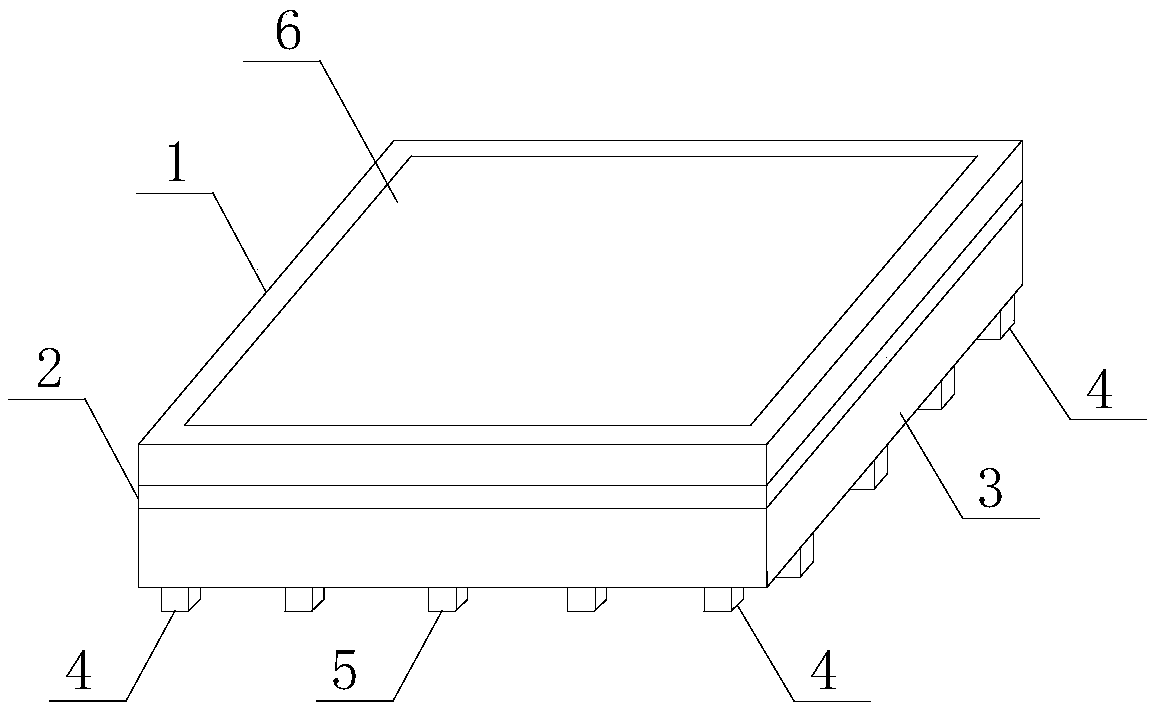
[0039] see figure 1 In this embodiment, the box bottom includes a functional layer 1 , a transition layer 2 , a buffer composite layer 3 , a corner connecting column 4 , a lattice pressure-bearing layer 5 and a grid leveling layer 6 .

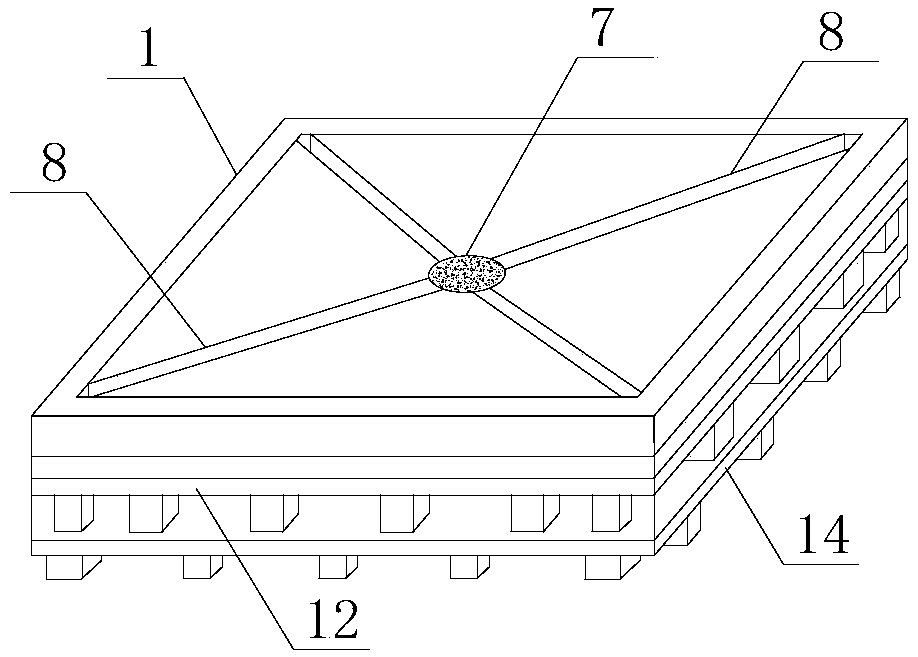
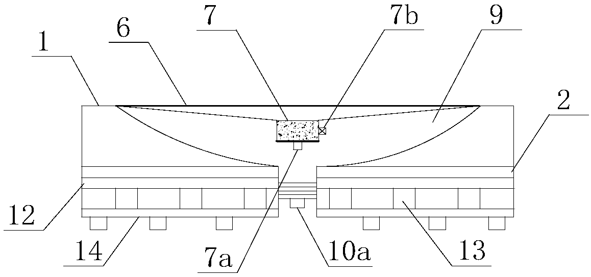
[0040] see Figure 2 to Figure 4 In this embodiment, a water collection filter hole 7 is provided in the center of the functional layer 1, and a diversion ditch 8 connected to the water collection filter hole 7 is provided on the functional layer 1. A functional chamber 9 connected to the water collection filter hole 7 is provided inside, a drip nozzle 7a is provided at the bottom of the water collection filter hole 7, and a water level monitoring device 7b is provided on one side of the water collection filter hole 7. ...


PUM

PropertyMeasurementUnit
Thicknessaaaaaaaaaa
Heightaaaaaaaaaa
Diameteraaaaaaaaaa

Abstract

The invention relates to a composite multifunctional box bottom structure. The composite multifunctional box bottom structure is characterized in that the box bottom comprises a function layer, a transition layer, a buffering composite layer, corner connecting columns, a lattice pressure bearing layer and a grid leveling layer. The function layer is provided with a water collecting filter hole, aflow guiding ditch and a function bin. The transition layer and the buffering composite layer are provided with a bolt hole and corner connecting holes. The buffering composite layer is composed of anupper load bearing plate, a lattice buffering layer and a lower load bearing plate from top to bottom. According to the composite multifunctional box bottom structure, vibration of the bottom of thebox can be eliminated and reduced, swinging of transportation objects in the box can be offset, and the effect of both-way vibration reduction is achieved. Meanwhile, condensate water generated in thetransportation process can be rapidly subjected to flow guiding and collecting, a refrigerant can be placed in the function bin, and the purposes of transportation object fresh keeping and cold storage are achieved. The structure is simple, cyclic utilization is facilitated, and wide applicability is achieved.

Description

technical field [0001] The invention belongs to the technical field of logistics transportation packaging, in particular to a composite multifunctional box bottom structure. Background technique [0002] In the field of logistics and transportation, in order to facilitate the storage and transportation of goods, the goods are generally placed in transport boxes for transportation. The goods are often damaged during transportation. The main reasons for the damage include the following aspects: [0003] First, when loading or unloading goods on or off the vehicle, the bottom of the transport box is in direct contact with the ground or the receiving surface. Since the total weight of the transport box is very large when it is fully loaded, a strong impact energy is generated at the moment of landing during loading and unloading, and the goods in the box are also subject to great vibration, which often causes damage to the goods in the box. [0004] Secondly, when using the tr...

Claims


Application Information

Patent Timeline
IPC IPC(8): B65D25/24B65D81/02B65D81/18B65D25/02B65D81/24B65D6/24
CPCB65D11/1866B65D25/02B65D25/24B65D81/02B65D81/18B65D81/24
Inventor 张美艳
Owner BOZHOU UNIV
Why Eureka
Try Eureka