Three-station medical bed pipe fitting automatic welding robot

An automatic welding and medical bed technology, applied in welding equipment, auxiliary welding equipment, welding/cutting auxiliary equipment, etc., can solve the problems of inconvenient installation and movement, large volume, etc., and achieve convenient disassembly and storage, small size and cost. low cost effect

Pending Publication Date: 2019-01-29
NANTONG HUALIANG FITNESS EQUIP CO LTD
View PDF1 Cites 0 Cited by
  • Summary
  • Abstract
  • Description
  • Claims
  • Application Information

AI Technical Summary

Problems solved by technology

However, this welding robot is bulky and inconvenient to install and move

Method used


Image

  • Three-station medical bed pipe fitting automatic welding robot
  • Three-station medical bed pipe fitting automatic welding robot
  • Three-station medical bed pipe fitting automatic welding robot

Examples


Embodiment 1

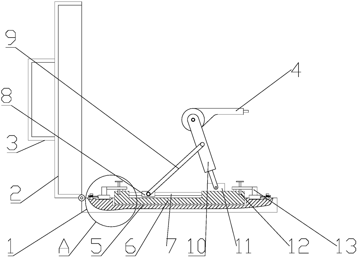
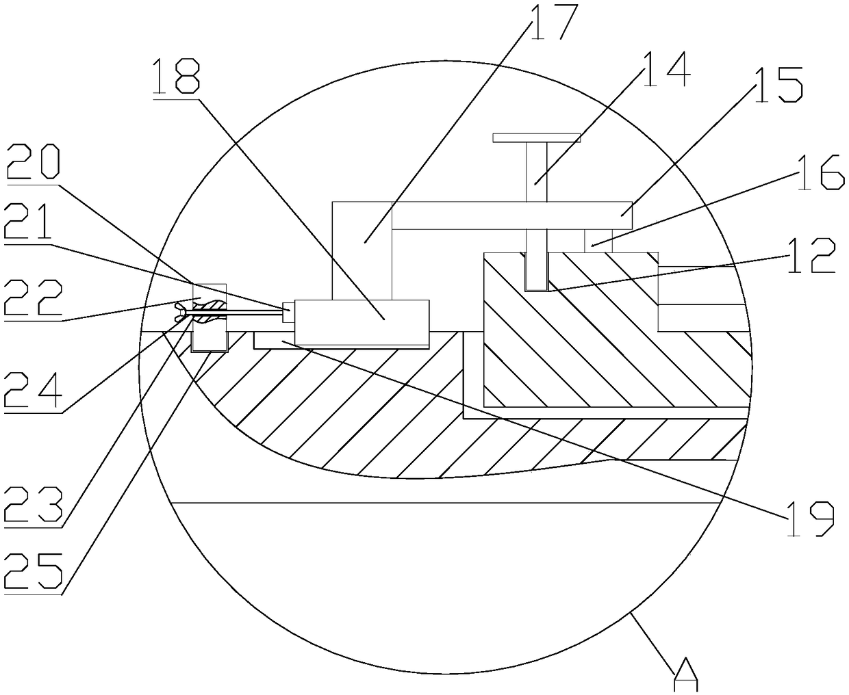
[0018] see figure 1 and figure 2 , a three-station medical bed pipe fittings automatic welding robot, including a base 1, a case cover 2, a handle 3 and a welding torch 4, the case cover 2 is rotatably mounted on the base 1, and the outer top bolts of the case cover 2 The handle 3 is fixed, the base 1 is provided with the welding torch 4; the base 1 is processed with a mounting groove 5, and a mounting platform 6 is placed in the mounting groove 5, and the mounting platform 6 is provided with There is a slide bar 7, a slide block 8 is installed to slide left and right on the slide bar 7, and the end of the connecting rod 9 is installed on the slide block 8, and the top end of the connecting rod 9 is rotatably installed on the column 10, and the column The bottom of 10 is rotatably installed on the boss 11, and the top of the column 10 is rotatably installed with the welding torch 4, so that the storage of the welding torch 4 can be realized by the rotation of the connecting ...

Embodiment 2

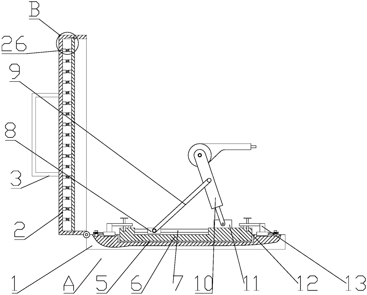
[0020] see image 3 and Figure 4 Compared with Embodiment 1, the difference between Embodiment 2 and Embodiment 1 is that the inner wall of the box cover 2 is provided with a shock absorbing mechanism 26 for buffering and shock absorbing during transportation, and the shock absorbing mechanism 26 includes a shock absorbing plate 27 , chute 28, spring seat 29, rod 30, spring 31 and sleeve 32, the damping plate 27 is slidably installed in the chute 28, and the chute 28 is opened on the left and right inner walls of the box cover 2 , the spring seat 29 is welded and fixed on the chute 28, the end of the rod 30 is welded and fixed on the spring seat 29, and the top end of the rod 30 is slidably installed in the sleeve 32, and the sleeve The cylinder 32 is welded and fixed on the top inner wall of the case cover 2 , and the spring 31 is sheathed on the outer side of the rod 30 .

[0021] The working principle of the present invention is: the storage of the welding torch 4 can be...


PUM


Abstract

The invention relates to the technical field of welding robots, in particular to a three-station medical bed pipe fitting automatic welding robot which comprises a base, a box cover, a holding handleand a welding gun. An installation groove is formed in the base, an installation table is placed in the installation groove and provided with a sliding rod, a sliding block is installed on the slidingrod in a left-right sliding mode, the tail end of a connection rod is rotationally installed to the sliding block, the top end of the connection rod is rotationally installed to a stand column, the bottom of the stand column is rotationally installed on a boss, the top of the stand column is rotationally provided with a welding gun, the installation table is provided with a limiting hole, and a fixing device is clamped into the limiting hole. The structure is simple, the cost is low, all the components are detachably installed, disassembling, assembly and storage are convenient, and the three-station medical bed pipe fitting automatic welding robot has the advantages of being small in size, easy to carry and convenient to install, and is quite high in practicability.

Description

technical field [0001] The invention relates to the technical field of welding robots, in particular to an automatic welding robot for three-station medical bed pipe fittings. Background technique [0002] Welding robots are industrial robots engaged in welding (including cutting and spraying). According to the definition of the International Organization for Standardization (ISO) that an industrial robot belongs to a standard welding robot, an industrial robot is a multipurpose, reprogrammable, automatic control manipulator with three or more programmable axes, used in the field of industrial automation . In order to adapt to different purposes, the mechanical interface of the last axis of the robot is usually a connecting flange, which can be connected to different tools or end effectors. The welding robot is equipped with a welding tongs or a welding (cutting) torch on the flange of the final axis of the industrial robot, so that it can perform welding, cutting or therm...

Claims


Application Information

Patent Timeline
Patent Type & Authority Applications(China)
IPC IPC(8): B23K37/02B23K101/06
CPCB23K37/02
Inventor 吴雪峰袁俊杰
Owner NANTONG HUALIANG FITNESS EQUIP CO LTD
Why Eureka
Try Eureka