
Current stabilizer

A flow stabilization device and circulating fluid technology, applied in pipeline systems, mechanical equipment, gas/liquid distribution and storage, etc., can solve problems such as limited pressure and flow adjustment range, large container volume, fatigue damage, etc., to ensure deformation capacity , high thermal stability and fast response

Pending Publication Date: 2019-01-25
STATE POWER INVESTMENT CORP RES INST
View PDF0 Cites 5 Cited by
  • Summary
  • Abstract
  • Description
  • Claims
  • Application Information

AI Technical Summary

Problems solved by technology

Among them, the manufacturing process of the airbag buffer is relatively complicated, and the airbag materials are mostly made of nitrile rubber, fluorine rubber, EPDM rubber, etc., which will cause high temperature aging, and the pressure and flow adjustment range is limited, which is not suitable for large flow and high temperature. The test circuit of the flat diaphragm buffer is high in reciprocating motion deformation frequency, which is prone to fatigue damage, and is not suitable for the test system with large flow, high pressure and high fluctuation frequency; the pressure-stabilizing container valve, water and gas in the same container Inside, the pressure in the container is adjusted by the gas in real time to ensure stable pressure, but for a circulating fluid circuit with a large flow rate, the container needs to be large in size, and water is prone to entrainment of the gas, resulting in a higher air bubble content in the circulating fluid circuit; The device that uses variable frequency pump for voltage stabilization, due to the response time of the sensor, the opening and closing of the pump valve, and the running time of the fluid in the pipeline, in the test system with a high frequency of pressure fluctuations, the pressure stabilization process has a time lag relative to the fluctuation of the flow rate

Method used


Image

  • Current stabilizer

Examples


Embodiment Construction

[0031] Embodiments of the present invention are described in detail below, examples of which are shown in the drawings, wherein the same or similar reference numerals designate the same or similar elements or elements having the same or similar functions throughout. The embodiments described below by referring to the figures are exemplary only for explaining the present invention and should not be construed as limiting the present invention.

[0032] In describing the present invention, it should be understood that the terms "center", "longitudinal", "transverse", "length", "width", "thickness", "upper", "lower", "front", " Back", "Left", "Right", "Vertical", "Horizontal", "Top", "Bottom", "Inner", "Outer", "Clockwise", "Counterclockwise", "Axial", The orientation or positional relationship indicated by "radial", "circumferential", etc. is based on the orientation or positional relationship shown in the drawings, and is only for the convenience of describing the present invent...


PUM


Abstract

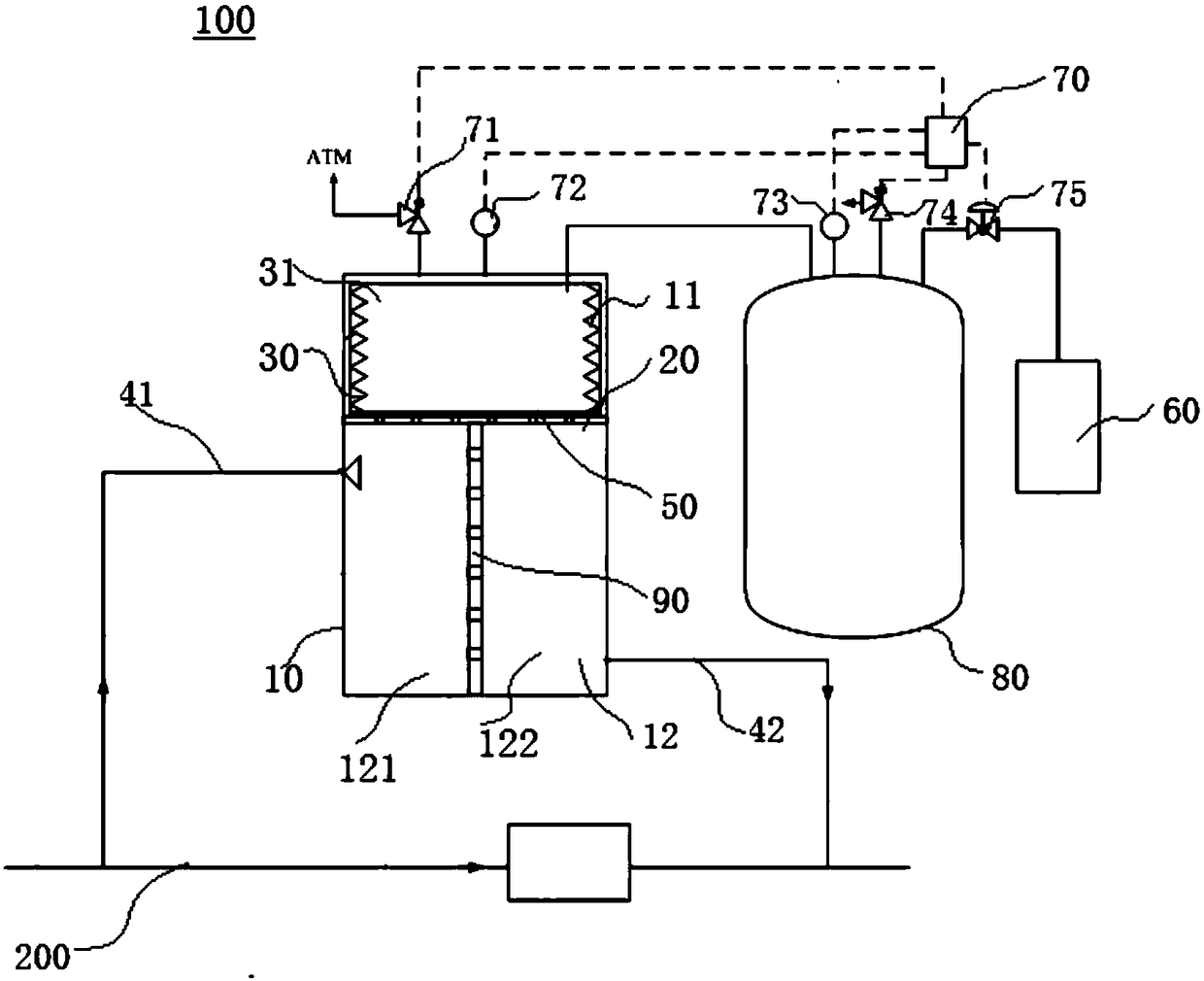
The invention discloses a current stabilizer, which comprises a shell, a first plate body, a deformable container, an air source and a controller, wherein the first plate body is arranged in the shellto divide a closed cavity into a first cavity and a second cavity which are mutually communicated, the deformable container is disposed within the first cavity and defines a gas chamber within the deformable container for containing gas, the gas chamber has a gas preload, the deformable container is configured to contract when the gas preload is less than a circulating liquid pressure within theshell, and to expand when the gas preload is greater than the circulating liquid pressure within the shell, the gas source is communicated with the gas chamber through a gas chamber connecting pipe, the controller is respectively connected with the gas source and the gas chamber, and the controller controls the gas source to provide gas to the gas chamber according to the pressure in a circulatingfluid loop so as to form gas prepressing. According to the current stabilizer provided by the embodiment of the invention, the flow and pressure fluctuation in the circulating fluid loop can be effectively absorbed, so that the stable flow of the circulating fluid in the circulating fluid loop is ensured, and the quality of a flow field is improved.

Description

technical field [0001] The invention relates to the technical field of circulating fluid circuit test systems, and more particularly, to a flow stabilization device. Background technique [0002] In the energy, electric power and chemical industries, due to the requirements of engineering verification, it is often necessary to carry out large flow, high temperature, high pressure tests. The test requires high flow, stable flow field and minimized flow fluctuation. However, in this large flow, high temperature, high pressure test system, due to the high power of the pump, it is easy to form a large pulse on the fluid, resulting in the pulsation of fluid pressure and flow; and the pipeline is more complicated, such as elbows, valves and other local resistance. More components generate disturbances, thereby enhancing fluid pressure and flow fluctuations. The pressure and flow fluctuations in the flow field will make it difficult to ensure a good flow field quality, which will ...

Claims


Application Information

Patent Timeline
IPC IPC(8): F17D1/02F17D3/01F17D5/00
CPCF17D1/02F17D3/01F17D5/00
Inventor 张谨奕王含刘云焰毛从清钟佳江小松
Owner STATE POWER INVESTMENT CORP RES INST
Learn More