
A wireless charging circuit and a charging control method for an electric vehicle

A wireless charging and electric vehicle technology, applied in electric vehicle charging technology, electric vehicles, battery/fuel cell control devices, etc., can solve problems such as equipment damage, manual operation, lack of coils, battery temperature control, etc.

Inactive Publication Date: 2019-01-22
CHINA THREE GORGES UNIV
View PDF11 Cites 6 Cited by
  • Summary
  • Abstract
  • Description
  • Claims
  • Application Information

AI Technical Summary

Problems solved by technology

The conductive type uses the cable as the transmission medium, and is connected by the cable and the coupler for direct contact power transmission, which requires manual operation, and the connection part is a vulnerable part, so the degree of safety has certain limitations; Quick battery replacement for semi-automatic mechanical equipment is costly and requires high standardization; the technology of wireless power transmission in space based on the principle of electromagnetic induction still has many defects
[0003] At present, the wireless charging facilities for electric vehicles lack effective means to ensure the efficient transmission of electric energy during the charging process, lack of temperature control for coils and batteries, and there are phenomena of equipment damage and fire accidents caused by excessive coil and battery temperatures.

Method used


Image

  • A wireless charging circuit and a charging control method for an electric vehicle
  • A wireless charging circuit and a charging control method for an electric vehicle
  • A wireless charging circuit and a charging control method for an electric vehicle

Examples


Embodiment Construction

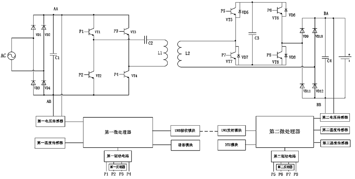
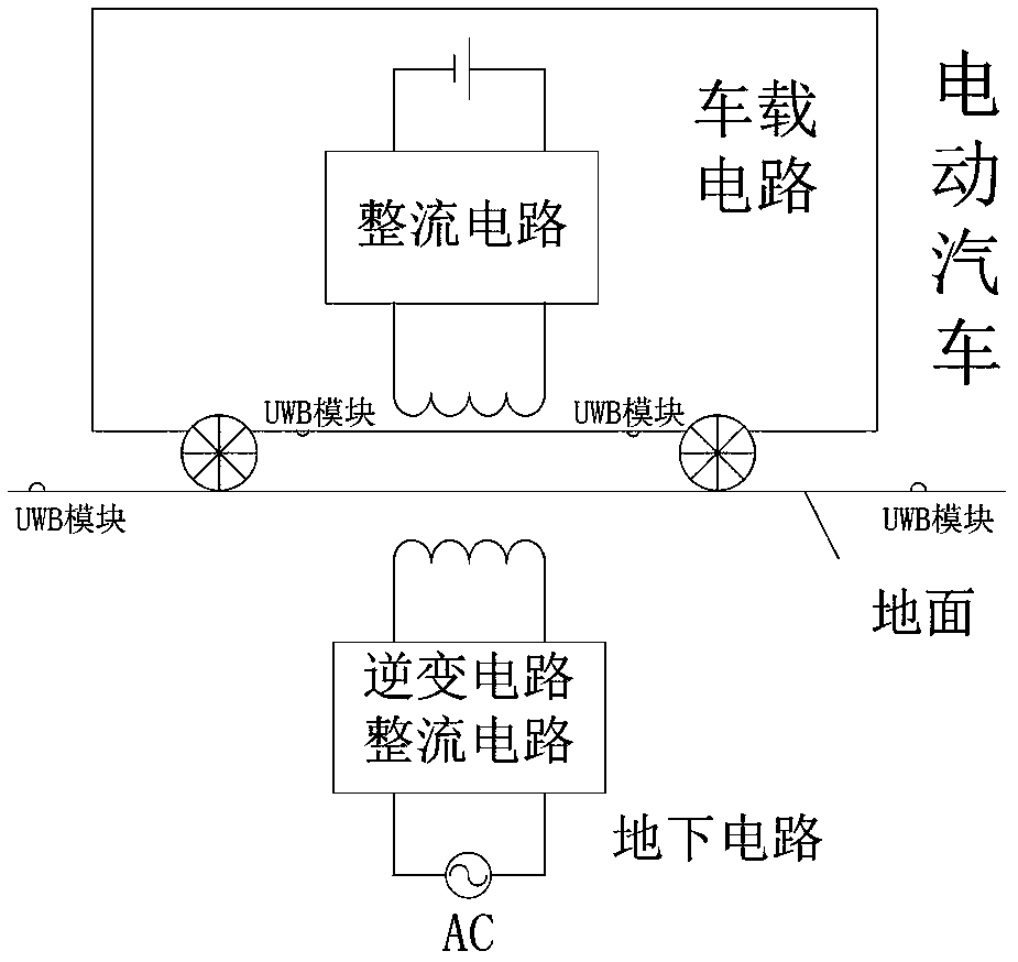
[0057] like figure 1 , figure 2 As shown, a wireless charging circuit for electric vehicles includes a transmitting circuit, a receiving circuit, a first control circuit, and a second control circuit. The control terminal of the transmitting circuit is connected to the first control circuit, and the control terminal of the receiving circuit is connected to the second control circuit. connection; the first control circuit communicates with the second control circuit.

[0058] The transmitting circuit includes a first rectifying circuit, an inverter circuit and a resonant circuit connected in sequence; the receiving circuit includes a coil L2, an electronic capacitor circuit, a second rectifying circuit and a lithium battery; A first voltage sensor connected to a microprocessor, a first drive circuit, a voice module, a first temperature sensor, and three UWB receiving modules; the second control circuit includes a second microprocessor and a second microprocessor connected res...


PUM


Abstract

A wireless charging circuit of an electric vehicle comprises a transmitting circuit, a receiving circuit and a control circuit, wherein an output end of the control circuit is respectively connected with a control end of a transmitting circuit and a control end of the receiving circuit, and an input end of the control circuit is respectively connected with a sampling output end of the transmittingcircuit and a sampling output end of the receiving circuit. The transmitting circuit comprises a first rectifier circuit, an inverter circuit and a harmonic oscillator circuit. The receiving circuitincludes a coil L2, an electronic capacitor circuit, a second rectifier circuit, and a battery. The invention adopts electronic capacitance, adjustable capacitance size, and realizes maximum chargingefficiency. The PCB coil is used to reduce the coil quality. the battery charge is accurately estimated so as to select the charging mode and prolong the service life of the rechargeable battery; UWBprecise positioning technology is used to improve the efficiency of wireless power transmission. the temperature of a battery and a coil is monitored to improve the safety of battery charging.

Description

technical field [0001] The invention belongs to the field of charging electric vehicles, and in particular relates to a wireless charging circuit and a charging control method for electric vehicles. Background technique [0002] There are currently three modes of electric vehicle charging on the market: conductive, inductive, and battery swapping. The conductive type uses the cable as the transmission medium, and is connected by the cable and the coupler for direct contact power transmission, which requires manual operation, and the connection part is a vulnerable part, so the degree of safety has certain limitations; The rapid battery replacement of semi-automatic mechanical equipment is costly and requires high standardization; the wireless power transmission technology in space based on the principle of electromagnetic induction still has many defects. [0003] At present, the wireless charging facilities for electric vehicles lack effective means to ensure the efficient...

Claims


Application Information

Patent Timeline
IPC IPC(8): H02J7/02H02J7/04H02J50/12H02J50/90B60L53/12B60L58/12
CPCH02J7/025H02J7/042H02J50/12H02J50/90H02J7/007192Y02T10/72Y02T10/70Y02T10/7072Y02T90/14
Inventor 魏业文戴帅龙单知非闵捷王琦婷侯希伦
Owner CHINA THREE GORGES UNIV
Learn More