A design method of turbine high speed shaft

A design method and high-speed shaft technology, applied in design optimization/simulation, calculation, special data processing applications, etc., can solve problems such as poor structural performance and long design cycle, achieve good structural performance, short design cycle, and reduce the number of cycles Effect

Pending Publication Date: 2019-01-22
WUHAN MARINE MACHINERY PLANT
View PDF3 Cites 4 Cited by
  • Summary
  • Abstract
  • Description
  • Claims
  • Application Information

AI Technical Summary

Problems solved by technology

[0004] The purpose of the present invention is to overcome the defects and problems of long design period and poor structural performance in the prior art, and provide a design method for a turbine high-speed shaft with a short design period and good structural performance

Method used


Image

  • A design method of turbine high speed shaft
  • A design method of turbine high speed shaft
  • A design method of turbine high speed shaft

Examples


Embodiment

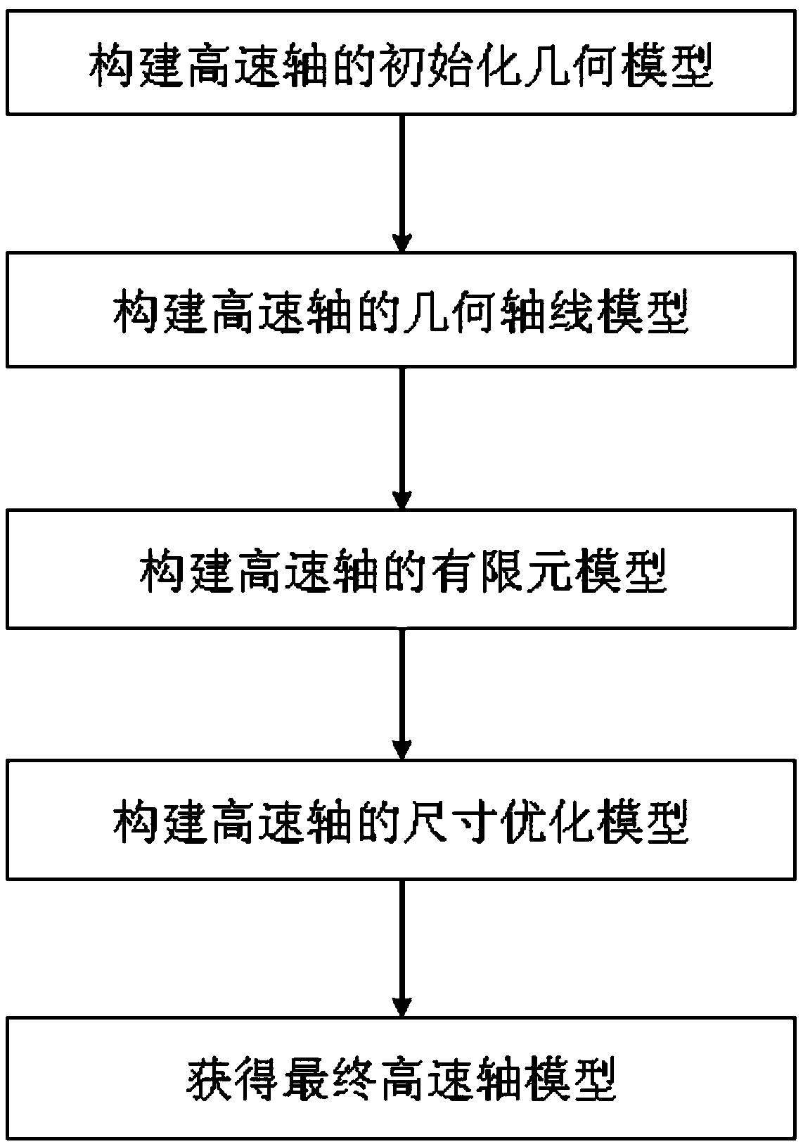
[0052] see figure 1 , a design method for a turbine high-speed shaft, the method comprising the following steps:

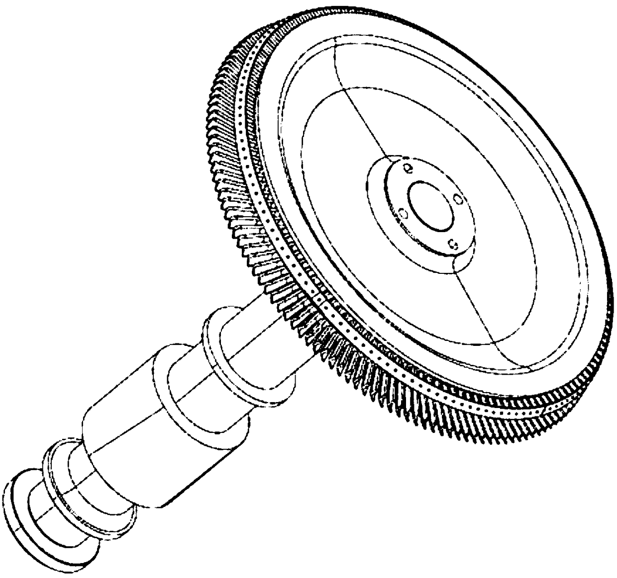
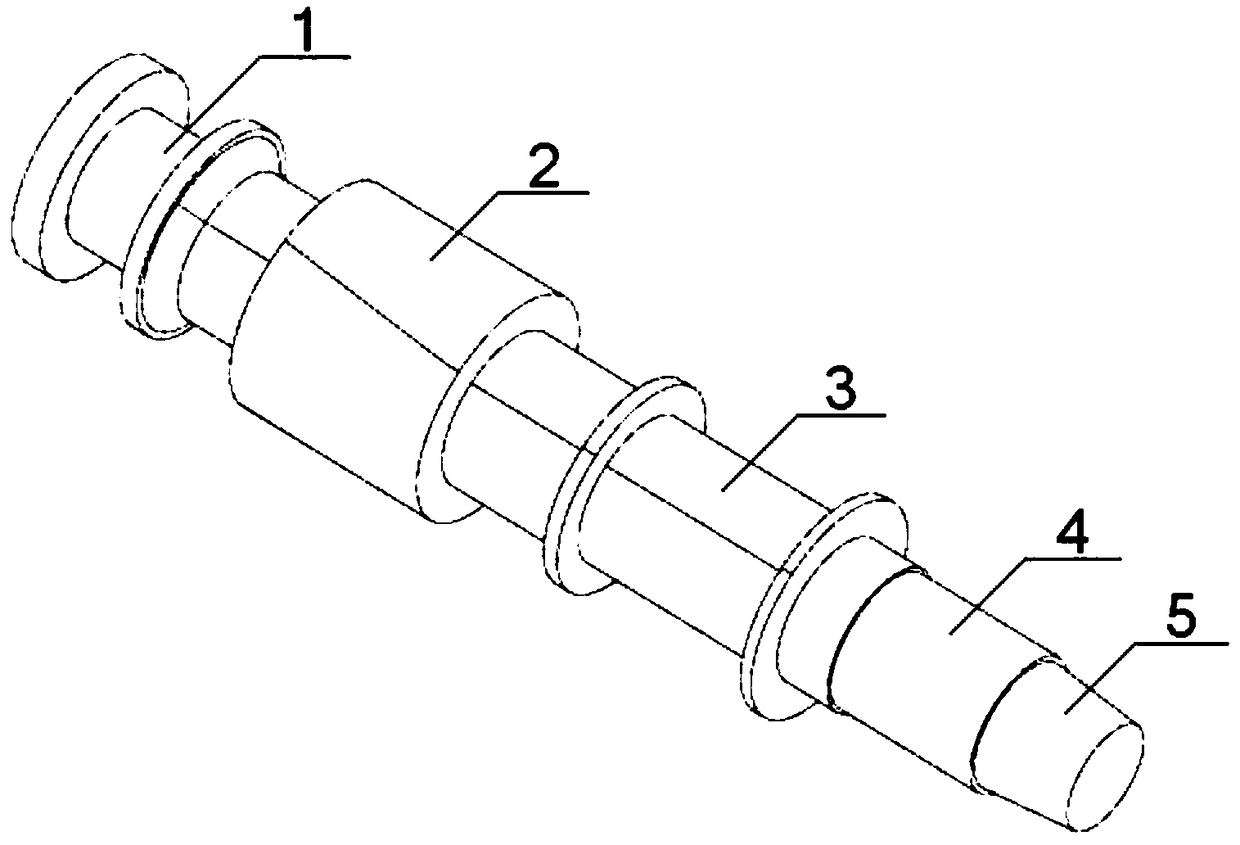
[0053] A. Construct the initialization geometric model of the high-speed axis

[0054] According to the design requirements and initial topology parameters, the initial geometric model of the high-speed shaft is obtained, and the initial geometric model is a three-dimensional solid model; the initial geometric model includes the No. 1 sliding bearing shaft section 1, the helical gear shaft section 2, and the No. 2 sliding bearing shaft Section 3, air seal shaft section 4, impeller assembly shaft section 5 and other intermediate transition shaft sections, such as figure 2 and image 3 shown;

[0055] B. Construct the geometric axis model of the high-speed shaft

[0056] Extract the axis of the initialization geometric model, and perform bonding processing to generate a geometric axis model of a high-speed axis composed of multiple axes, such as Figure 4 show...


PUM


Abstract

A design method of a turbine high speed shaft. The method comprises the following steps: according to the design requirements and the initial topology parameters, the initialization geometry model ofthe high-speed shaft is obtained, then the initialization geometric model axis is extracted, the adhesive treatment is carried out, a geometric axis model of a high-speed shaft composed of multiple axes is generated, the material attribute and the cross-sectional outer diameter of that geometrical axis model are then imparted, a finite element method is used to discretize the geometrical axis model, and the boundary conditions are imposed, the finite element model of high speed shaft is obtained, then, according to the structural performance requirements of the high-speed shaft, the size optimization model of the high-speed shaft is constructed, and then the size optimization model is solved to obtain the high-speed shaft optimization model, and the structural performance of the high-speed shaft optimization model is checked, and the local adjustment is carried out according to the checking result, and finally the high-speed shaft model satisfying the structural performance requirements is obtained. This design not only has short design period and high design benefit, but also has good structural performance.

Description

technical field [0001] The invention relates to the field of turbine machinery design, in particular to a design method for a turbine high-speed shaft, which is mainly suitable for shortening the design cycle and improving structural performance. Background technique [0002] The high-speed shaft is the main functional part of the turbine, which plays the role of installing and fixing the impeller and transmitting power. The high-speed shaft design not only needs to ensure structural strength and stability, but also needs to keep its weight as low as possible. The common design method now is to first establish the initial geometric model of the high-speed shaft based on experience or analogy with a high-speed shaft with a similar structure, then perform a simulation check on the structural strength and critical speed, and then perform a simulation check on each axis of the high-speed shaft based on the simulation check. The section diameter is adjusted and checked repeatedl...

Claims


Application Information

Patent Timeline
Patent Type & Authority Applications(China)
IPC IPC(8): G06F17/50
CPCG06F30/23
Inventor 傅显钧覃刚王强赵君龙
Owner WUHAN MARINE MACHINERY PLANT
Why Eureka
Try Eureka