Light fully assembled large cantilever ultra-high performance concrete wing beam and its construction method

An ultra-high-performance, fully-assembled technology, applied in the direction of erecting/assembling bridges, bridges, bridge construction, etc., can solve problems such as high requirements for transportation equipment and lifting equipment, difficulties in transportation and installation of prefabricated components, and greater impact on the surrounding environment , to achieve the effect of convenient assembly process, convenient and fast construction, and shortened construction period

Active Publication Date: 2020-04-14
HUNAN UNIV
View PDF6 Cites 0 Cited by
  • Summary
  • Abstract
  • Description
  • Claims
  • Application Information

AI Technical Summary

Problems solved by technology

[0002] At present, most bridges in our country are constructed by in-situ pouring. On-site pouring has the advantages of no need for large lifting equipment, stable and reliable construction, and good bridge integrity. As another common method of bridge construction, prefabricated installation has the advantages of short construction time, good quality prefabricated components, environmental protection and energy saving compared with cast-in-place
However, the transportation and installation of prefabricated components are often difficult during the prefabricated installation construction process, and the requirements for transportation equipment and lifting equipment are relatively high, which increases the cost

Method used


Image

  • Light fully assembled large cantilever ultra-high performance concrete wing beam and its construction method
  • Light fully assembled large cantilever ultra-high performance concrete wing beam and its construction method
  • Light fully assembled large cantilever ultra-high performance concrete wing beam and its construction method

Examples


Embodiment

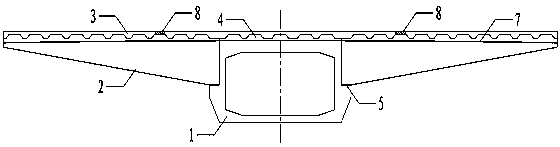
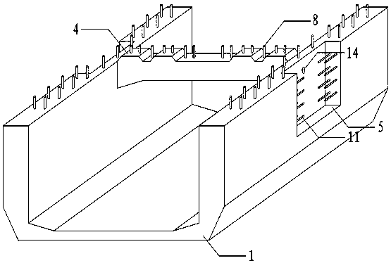
[0037] refer to Figure 1~10 : Light fully assembled large cantilever ultra-high performance concrete wing beam, including trough beam 1, tooth-shaped variable-section cantilever beam 2 and wave-rib bridge deck 3, the trough-shaped beam 1, tooth-shaped variable-section cantilever beam 2 and wave-rib bridge The panel 3 is an ultra-high performance concrete (UHPC) prefabricated component. The top outer surface of the web of the channel beam 1 is provided with a splicing groove 5 connected to the tooth-shaped variable-section cantilever beam 2. There is a transverse beam 4 on the side; the top of the transverse beam 4 is tooth-shaped, and the anchor bolts 8 for splicing with the bridge deck are embedded in advance; The anchor bolts 8 spliced ​​with the bridge deck; the wave-rib bridge deck 3 is assembled from several prefabricated bridge decks, and the wave-shaped ribs at the bottom match the teeth on the top of the groove-shaped beam 1 and the tooth-shaped variable-section canti...


PUM


Abstract

The invention provides a fully-assembled light-weight large cantilever ultra-high performance concrete spread-wing beam, which comprises a channel beam, a toothed variable cross-section cantilever beam and a corrugated rib bridge deck, wherein the channel beam, the toothed variable cross-section cantilever beam and the corrugated rib bridge deck are ultra-high performance concrete precast members,a splicing groove connected with the toothed variable cross-section cantilever beam is arranged on the top outer side of the web of the channel beam, and a cross beam is arranged on the inner side ofthe web opposite to the splicing groove; The top of the diaphragm and the top of the cantilever beam with toothed variable cross-section are toothed and embedded with anchor bolts for splicing with the bridge deck. The corrugated rib bridge deck is assembled with several prefabricated bridge decks. The corrugated ribs at the bottom of the prefabricated bridge deck are matched with the teeth on the top of the channel beam and the cantilever beam with tooth shape and variable cross-section, and bolt holes are reserved. The splicing groove and the splicing place of the precast bridge deck are poured with ultra-high performance concrete to form wet joints. The invention also discloses a construction method of the spread-wing beam. The spreading wing beam is beautiful in appearance, lightweight and excellent in stretching performance, durability up to more than 200 years, and simple in construction.

Description

technical field [0001] The invention relates to the technical field of bridge engineering, in particular to a light fully assembled large cantilever ultra-high performance concrete wing beam. Background technique [0002] At present, most bridges in our country are constructed by in-situ pouring. On-site pouring has the advantages of no need for large lifting equipment, stable and reliable construction, and good bridge integrity. As another common method of bridge construction, prefabricated installation has the advantages of short construction time, good quality of prefabricated components, environmental protection and energy saving compared with on-site pouring. However, the transportation and installation of prefabricated components are often difficult during the prefabricated installation construction process, and the requirements for transportation equipment and lifting equipment are relatively high, which increases the cost. It can be seen that a light fully assembled...

Claims


Application Information

Patent Timeline
Patent Type & Authority Patents(China)
IPC IPC(8): E01D2/00E01D21/00
CPCE01D2/00E01D21/00
Inventor 张阳徐子兵李星亮朱平邵旭东
Owner HUNAN UNIV
Why Eureka
Try Eureka