
Rapid forming process of large flange of high-power wind power main shaft

A technology of wind power spindle and forming process, which is applied in manufacturing tools, metal processing equipment, forging/pressing/hammer devices, etc. Mechanical properties, improve the density of the tissue, increase the effect of the drawing ratio

Inactive Publication Date: 2019-01-18
JIANGYIN NANGONG FORGING
View PDF6 Cites 6 Cited by
  • Summary
  • Abstract
  • Description
  • Claims
  • Application Information

AI Technical Summary

Problems solved by technology

[0008] Therefore, in view of the technical problems in the prior art that the wind power main shaft passes through the conventional shaft free forging method, the machining allowance is large, the cost is high, and the performance of the large flange cannot be guaranteed, the purpose of the present invention is to provide a large flange for a high-power wind power main shaft Rapid prototyping process can effectively reduce machining allowance and cost, while ensuring the performance of large flanges

Method used


Image

  • Rapid forming process of large flange of high-power wind power main shaft
  • Rapid forming process of large flange of high-power wind power main shaft
  • Rapid forming process of large flange of high-power wind power main shaft

Examples


Embodiment 1

[0041] The forging technological process of the present invention is as image 3 shown, including steps:

[0042] (1) Casting steel ingot blanks, including octagonal material 101 with a large upper end and a small lower end and a riser 102 at the upper end, the octagonal material 101 has an octagonal cross section and a trapezoidal longitudinal section; then cut off the nozzle and cut off the riser flash;

[0043] (2) The first fire forging

[0044] 2a) The billet is put into the furnace and heated to 1170-1230°C, kept for 7-12 hours before being released from the furnace;

[0045] 2b) Press the riser 102 into a clamp handle 103, and upset the drain plate 11 (the clamp handle 103 is placed in the leak hole of the drain plate 11), and the height H of the square material 101 after upsetting is 0.4 to 0.6 times the original length , and then extended to 1.7-2.3H;

[0046] 2c) Then enter the leaking plate and upset to the height H, then pull it out, and cut out the material dis...


PUM


Abstract

The invention discloses a rapid forming process of a large flange of a high-power wind power main shaft. The process comprises the steps of (1) casting of a steel ingot blank material, wherein the steel ingot blank material includes a main body and a riser, then a water opening is cut off, and the trim part of the riser is cut off; (2) preliminary forging on fire, wherein a blank material feedingfurnace is heated to 1170-1230 DEG C, the temperature is kept for 7-12 hours, upsetting is conducted until the height is H, pulling is conducted until the blank material is 1.7-2.3H long, then upsetting is conducted again until the height is H, and branch materials in eight directions are pulled; (3) secondary forging on fire, wherein the blank material is sent back to the furnace for being heatedto 1170-1230 DEG C, the temperature is kept for 5-10 hours, then steps are pulled out, the riser is thermally cut, and the blank material is placed in a padding mold and a flange mold and forged andformed to obtain the large flange by adopting a partial upsetting mode. The process can effectively solve problems in free forging methods of conventional shafts, rapid forming of the large flange endof the high-power wind power main shaft is achieved, the machining allowance is small, there is no need to consider the problem of drawing out a concave core, and the tangential performance of the large flange of the wind power main shaft can be effectively improved.

Description

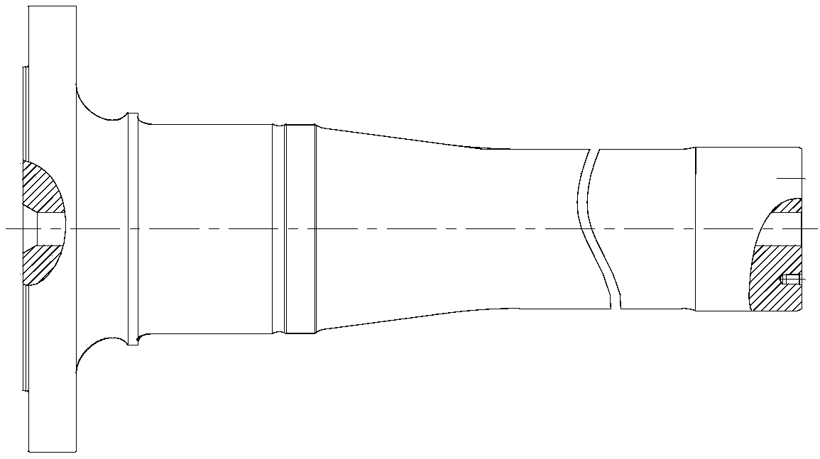
technical field [0001] The invention belongs to the technical field of wind power main shaft forging, and in particular relates to a rapid prototyping process of a large flange of a high-power wind power main shaft. Background technique [0002] The wind power main shaft is the core component connecting the fan blades and the speed-increasing gearbox, and is the core component of the high-power wind turbine. The commonly used shapes of wind power main shaft are as follows: figure 1 and figure 2 As shown, one end is a large flange, and the other end is a stepped shaft section, and the junction between the stepped shaft section and the large flange is a large transition arc. The large difference between the outer diameter of the large flange and the outer diameter of the stepped shaft section makes the forging of the wind power main shaft more difficult. According to the conventional shaft free forging method, the following needs to be considered: [0003] 1. It is easy to...

Claims


Application Information

Patent Timeline
Patent Type & Authority Applications(China)
IPC IPC(8): B21J5/00B21J5/08B21J5/06B21J13/02
CPCB21J5/002B21J5/06B21J5/08B21J13/02
Inventor 高明邱亚军薛松周沁怡陈刚高欣
Owner JIANGYIN NANGONG FORGING
Learn More