A single-rotation permanent magnet clamped linear stepping piezoelectric actuator and a driving method of the actuator
A piezoelectric driver and linear stepping technology, applied in the direction of piezoelectric effect/electrostrictive or magnetostrictive motors, generators/motors, electrical components, etc., can solve the problems of short life, complex electronic control of the driver and mechanical structure , low resolution and other problems, to achieve the effect of long service life, novel method and high resolution
- Summary
- Abstract
- Description
- Claims
- Application Information
AI Technical Summary
Problems solved by technology
Method used
Image
Examples
specific Embodiment approach 1
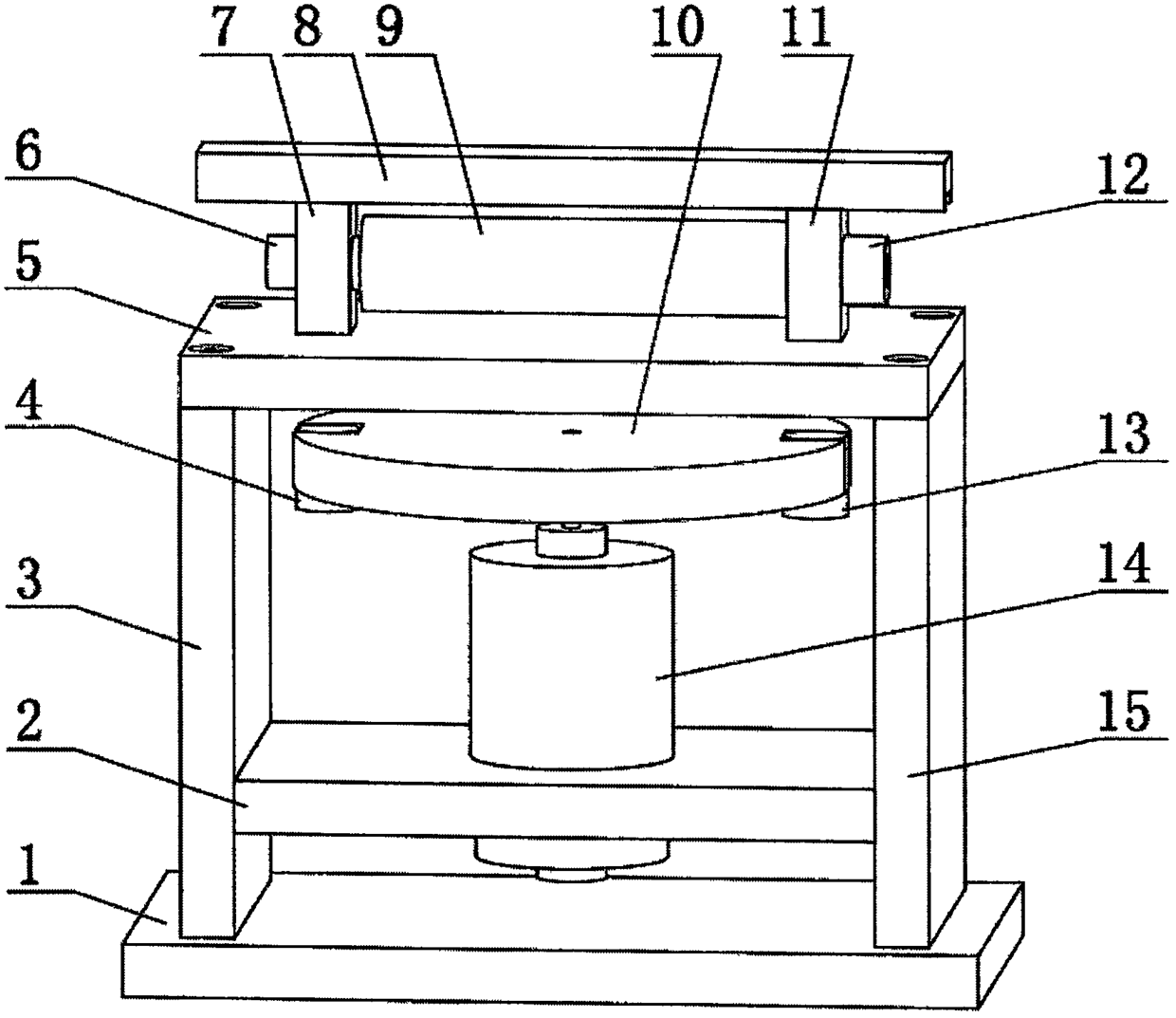
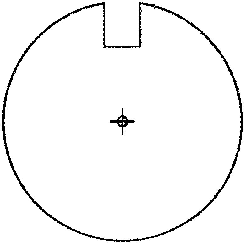
[0033] Specific implementation mode one: refer to Figure 1 to Figure 4 Specifically explain this embodiment, a single-rotation permanent magnet clamp linear stepping piezoelectric driver described in the embodiment, which includes: a base 1, a DC motor bracket 2, a DC motor 14, a rotating magnet fixed disk 10, and a magnet 4 , mass block 13, support plate A3, support plate B15, working surface plate 5, piezoelectric stack 9, sliding magnetic block 7, fixed magnetic block 11, pre-tightening screw 6, pre-tightening screw 12, moving steel bar 8 ;
[0034] The moving part is a moving steel bar 8, which is placed on the sliding magnetic block 7 and the fixed magnetic block 11;
[0035] The driving part is composed of a working surface plate 5, a piezoelectric stack 9, a sliding magnetic block 7, a fixed magnetic block 11, a pre-tightening screw 6, and a pre-tightening screw 12. The bottom of the fixed magnetic block 11 is designed with a threaded hole, through which the screw Fi...
specific Embodiment approach 2
[0042] Specific implementation mode two: refer to Figure 5 , Figure 6 , Figure 7Specifically illustrate this embodiment, a driving method of a single-rotation permanent magnet clamp linear stepping piezoelectric driver described in the specific embodiment, the method is:
[0043] When the magnet 4 in the time-sharing clamping magnetic field rotates to below the fixed magnetic block 11 as Figure 7 As shown in (1), the piezoelectric stack 9 is not energized at this moment, and the excitation signal of the piezoelectric stack 9 is Figure 6 In section a-b in the middle, when the magnet 4 rotates to the bottom of the sliding magnetic block 7, the piezoelectric stack 9 is continuously energized as Figure 6 Middle section c-d, at this time, the piezoelectric stack 9 will elongate simultaneously with the left sliding magnetic block 7, and due to the magnetic force, it will drive the upper moving steel bar 8 to slide one step to the left. Figure 7 as shown in (2);
[0044] ...
PUM
 Abstract
Description
Claims
Application Information
 - R&D Engineer
- R&D Manager
- IP Professional
- Industry Leading Data Capabilities
- Powerful AI technology
- Patent DNA Extraction
Browse by: Latest US Patents, China's latest patents, Technical Efficacy Thesaurus, Application Domain, Technology Topic, Popular Technical Reports.
© 2024 PatSnap. All rights reserved.Legal|Privacy policy|Modern Slavery Act Transparency Statement|Sitemap|About US| Contact US: help@patsnap.com


