
Shaft reflective pulse laser beam combiner and pulse beam combiner laser system

A technology of laser beam combiner and pulse laser, which is applied in the field of laser, can solve the problems that it is difficult to adapt to the impact of high-power laser beam quality, and achieve the effects of easy engineering implementation, improved laser tolerance, and increased power and repetition frequency

Active Publication Date: 2020-08-14
NORTHWEST INST OF NUCLEAR TECH
View PDF9 Cites 0 Cited by
  • Summary
  • Abstract
  • Description
  • Claims
  • Application Information

AI Technical Summary

Problems solved by technology

[0007] The purpose of the present invention is to overcome the defect that the transmissive element is difficult to adapt to the high-power laser in the existing pulse sequence beam combining or the defect that other beam combining methods affect the beam quality after beam combining, and proposes a rotating shaft reflector Type pulse laser beam combiner and pulse beam combiner laser system, which greatly improves the average output power and repetition rate of a single laser, and basically keeps the beam quality of the original laser unchanged, and has good power and laser quantity scalability

Method used


Image

  • Shaft reflective pulse laser beam combiner and pulse beam combiner laser system
  • Shaft reflective pulse laser beam combiner and pulse beam combiner laser system
  • Shaft reflective pulse laser beam combiner and pulse beam combiner laser system

Examples


Embodiment Construction

[0037] The present invention will be described in detail below in conjunction with the accompanying drawings and specific embodiments.

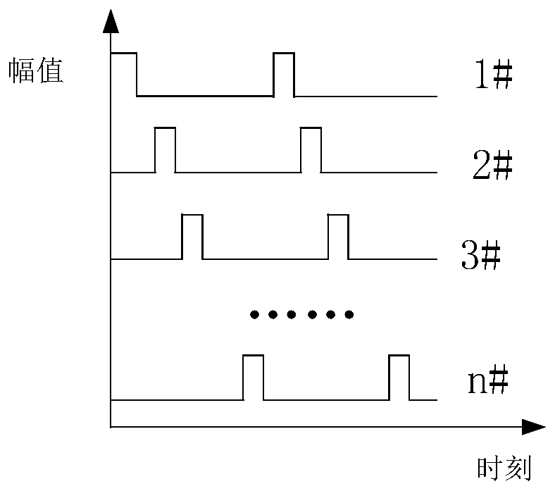
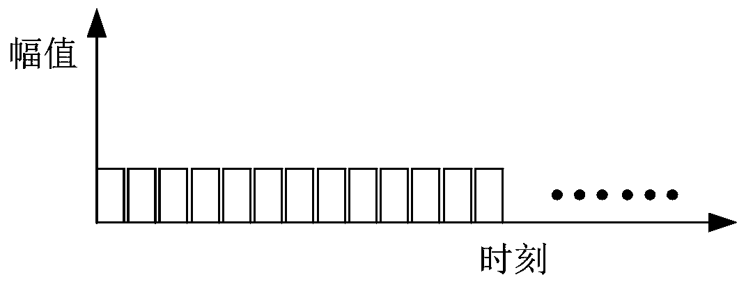
[0038] Such as figure 1 , figure 2 with image 3 As shown, the principle idea of ​​pulse combining in the present invention is: on the same output optical path 4, n reflectors 2 are obliquely arranged, and each reflector 2 is arranged on the displacement device 1, and can make the reflector 2 along the In the mirror shifting direction 3, move out of the beam combining optical path and then move back to the beam combining optical path, the beam combining optical path is the output optical path 4; the shifting device 1 can be an integral mechanism or a split mechanism, which can realize 2 mirrors each independent movement in and out.

[0039] Each reflector 2 corresponds to the incident laser beam 3, where the laser is a pulsed laser output at a repeated frequency, and the light output timing of each laser is as follows figure 2 As shown,...


PUM

PropertyMeasurementUnit
angleaaaaaaaaaa
angleaaaaaaaaaa

Abstract

The invention relates to a rotating shaft reflection type pulsed laser beam combiner and a pulse beam combination laser system. In order to overcome the defects in the existing pulse timing sequence beam combination that a transmission type component is difficult to adapt to high-power laser or the defects that other beam combination methods affect the beam quality after the beam combination, theinvention provides a beam combiner for pulse laser. The beam combiner comprises a rotating shaft and reflectors fixed thereon, wherein the axial lead of the rotating shaft is parallel to a combined beam, the reflectors are arranged along the axial lead of the rotating shaft at intervals and are distributed along the radial direction in a stagger manner by using the axle center as the circle center; and multiple beams of pulse laser are reflected by the corresponding reflectors and are emitted along an output light path after being combined in the space. The invention further provides a pulsebeam combination laser system, consisting of the beam combiner, multiple pulse lasers and multiple foldback mirrors, wherein the pulse lasers emit laser according to a set timing sequence, and the laser is incident to the reflectors after being returned by the foldback mirrors to form combined laser for emitting.

Description

technical field [0001] The invention belongs to the technical field of lasers, and in particular relates to a shaft reflective pulse laser beam combiner and a pulse beam combiner laser system. Background technique [0002] With the continuous development and maturity of laser technology, high-power lasers have become more and more widely used, which has profoundly affected the development of many industries. According to the working mode, high-power lasers are mainly divided into high-peak-power lasers (that is, high-energy pulsed lasers) and high-average power lasers. [0003] For high-energy pulsed lasers, lasers are required to have a certain repetition rate in various application fields. However, directly increasing the repetition rate of high-energy pulsed laser operation will cause serious thermal effects, which will affect the performance of the laser, and even lead to a decrease in the output pulse energy of the laser. can not work. For high-average-power lasers, a...

Claims


Application Information

Patent Timeline
Patent Type & Authority Patents(China)
IPC IPC(8): G02B26/08G02B27/09G02B27/10H01S3/10
CPCG02B26/0816G02B27/0977G02B27/10H01S3/10
Inventor 陈绍武杨鹏翎王振宝吴勇冯刚闫燕武俊杰谢贤忱
Owner NORTHWEST INST OF NUCLEAR TECH
Learn More