Optical fiber laser group beam laser

A fiber laser and laser technology, applied in the direction of lasers, laser devices, laser components, etc., can solve the problems of complex optical path, large loss of optical energy, low system stability, etc., and achieve the effect of simple optical path and reduced optical components

Inactive Publication Date: 2006-12-27
SHANGHAI INST OF OPTICS & FINE MECHANICS CHINESE ACAD OF SCI
View PDF0 Cites 0 Cited by
  • Summary
  • Abstract
  • Description
  • Claims
  • Application Information

AI Technical Summary

Problems solved by technology

In the prior art, the designed external cavity has a spatial filter, which requires two lenses and a separate semi-transparent mirror, see the prior art [IEEE J.QuantumElectron.Vol.27:1582-1593, 1991], this This kind of external cavity can coherently couple the output laser light of the fiber array, but the optical path is complicated, the distance between all optical components needs to be strictly controlled, the stability of the whole system is not high, and it is difficult to realize. In addition, because the beam is in the resonator When going back and forth, passing through the surface of each component multiple times, the loss of light energy is relatively large, which is not conducive to the improvement of the power of the entire system

Method used


Image

  • Optical fiber laser group beam laser
  • Optical fiber laser group beam laser
  • Optical fiber laser group beam laser

Examples


Embodiment Construction

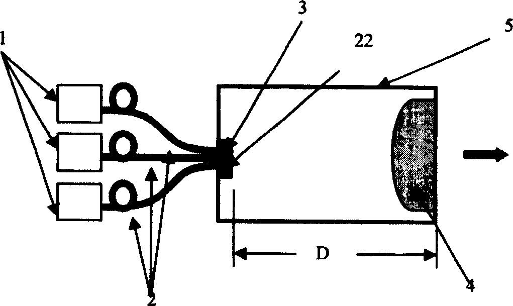
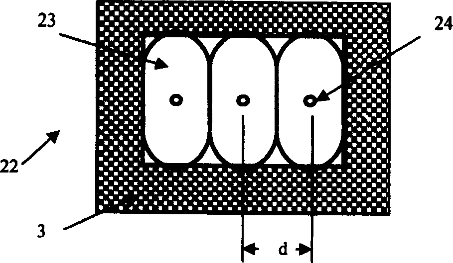
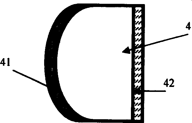
[0012] see first figure 1 , figure 1 It is a structural schematic diagram of the fiber laser bundle laser used in the present invention. As can be seen from the figure, the fiber laser bundle laser of the present invention comprises a plurality of double-clad optical fibers 2, and one end of each double-clad optical fiber 2 is respectively connected to a pump laser 1, and is characterized in that the plurality of double-clad optical fibers After the outer cladding is removed from the other end of the optical fiber 2, the line array is closely arranged in the optical fiber holder 3 to form a flat optical fiber array output end face 22 and placed in one end of a resonant cavity box 5, and the other end of the resonant cavity box 5 is provided with a plano-convex lens 4. The convex surface of the plano-convex lens 4 is coated with an anti-reflection film 41, and the plane is coated with a semi-transparent reflective film 42 toward the outside of the resonant cavity box 5. Form ...


PUM


Abstract

A optical fiber beam laser includes multiple double clad optical fibers, one end of each optical fiber is connected with a pump laser, the other ends of the optical fibers are closely arrayed in a optical fiber clamp in linearity to form a flat optical fiber array output end face and put in an end of a resonator box after removing the clad, a flat convex lens is set at the other end of the box coated with antireflection film on the convex face and the plane face is coated with semi-transparent reflection film toward outside of the box, the distance of the optical fiber array output end face to the semi-transparent reflection film is D, the distance between the fiber cores is d, focal distance of the lens is F forming the following formula: sqd(lambda / 2) F and D=F / 2.

Description

technical field [0001] The invention relates to a fiber laser, in particular to a fiber laser group laser. Background technique [0002] Among various techniques for coherent combination of laser beams, coherent beam combination using an external cavity is a very useful technique. In the prior art, the designed external cavity has a spatial filter, which requires two lenses and a separate semi-transparent mirror, see the prior art [IEEE J.QuantumElectron.Vol.27:1582-1593, 1991], this This kind of external cavity can coherently couple the output laser light of the fiber array, but the optical path is complicated, the distance between all optical components needs to be strictly controlled, the stability of the whole system is not high, and it is difficult to realize. In addition, because the beam is in the resonator When going back and forth, passing through the surface of each component multiple times, the loss of light energy is relatively large, which is not conducive to t...

Claims


Application Information

Patent Timeline
Patent Type & Authority Patents(China)
IPC IPC(8): H01S3/08H01S3/23H01S3/067H01S3/0941
Inventor 楼祺洪何兵周军叶震寰陈慧挺孔令峰
Owner SHANGHAI INST OF OPTICS & FINE MECHANICS CHINESE ACAD OF SCI
Why Eureka
Try Eureka