A method for autonomous verification of fiber optic gyroscope detection circuit

A fiber optic gyroscope and detection circuit technology, which is used in the measurement of electricity, measurement of electrical variables, and electronic circuit testing. The effect of small circuit complexity and easy performance improvement

Active Publication Date: 2020-07-14
BEIJING INST OF CONTROL ENG
View PDF6 Cites 0 Cited by
  • Summary
  • Abstract
  • Description
  • Claims
  • Application Information

AI Technical Summary

Problems solved by technology

[0008] Method (1) relies on the cooperation of the optical fiber loop, which leads to the inability to effectively decouple the verification of the circuit part from the optical circuit part, thus affecting product development
And in the case of problems in the product development process, it is impossible to quickly decouple the positioning problem, thus further affecting the product development process;
[0009] Method (2) lacks targeted tests for hardware, such as the design and analysis of performance index test schemes that have a greater impact on modulation and demodulation, such as delay links;
[0010] Method (2) lacks targeted verification for each module of the hardware, resulting in the final verification result for the entire circuit, unable to find key modules that affect product performance, which may lead to "performance problems, it is difficult to locate each module" or " Performance improvement, unable to find key factors", lack of practical application value

Method used


Image

  • A method for autonomous verification of fiber optic gyroscope detection circuit
  • A method for autonomous verification of fiber optic gyroscope detection circuit
  • A method for autonomous verification of fiber optic gyroscope detection circuit

Examples


Embodiment

[0067] An independent verification method for an optical fiber gyroscope detection circuit, the steps of the method include:

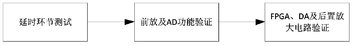
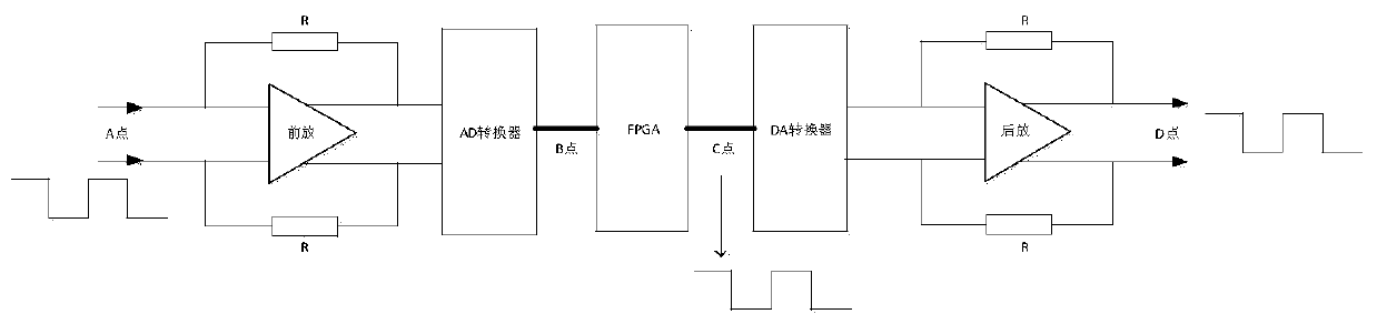
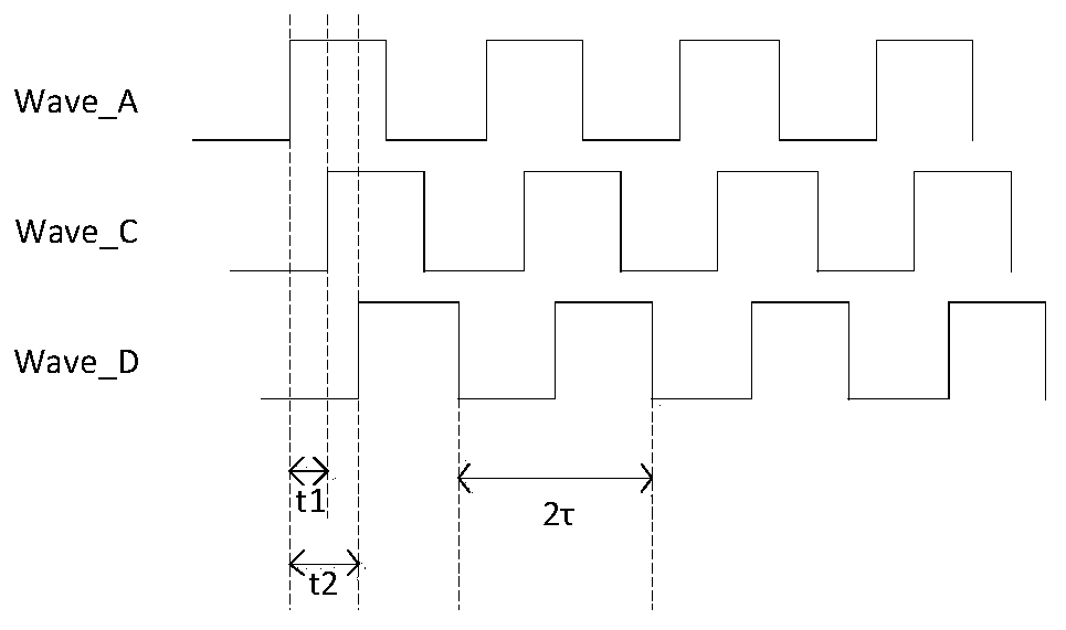
[0068] (1) According to the attached figure 2 To build the fiber optic gyroscope detection circuit system, first test the delay link of the system;

[0069] (2) For the current product, the circuit application scenario is set to a ring length of about 580m, then the eigenfrequency f=c / (2n*l)≈178.4KHz; at the same time, confirm the frequency f of the external crystal oscillator according to the common specifications out =N*f=96*178.4KHz≈17.126MHz, take f nearby out =17.152MHz, and the design value of the reversed eigenfrequency is f=17152KHz / 96=178.67KHz.

[0070] (3) Make the AD acquisition clock signal ad_clk, the selected AD maximum conversion frequency f admax =3MHz, then according to N 3 constraint, take f ad =12*f=2.144MHz.

[0071] (4) Make the DA acquisition clock signal da_clk, the maximum conversion frequency of the selected DA is 30MHz, ...


PUM


Abstract

The invention discloses an autonomic verification method for a fiber-optic gyroscope detection circuit. The method comprises the following steps that: firstly, constructing a fiber-optic gyroscope detection circuit, determining the intrinsic frequency of the fiber-optic gyroscope and the external crystal oscillation frequency of the fiber-optic gyroscope detection circuit, and manufacturing an AD(Analog-to-Digital) convertor and a DA convertor to collect a clock signal; then, carrying out testing and calculation to obtain the time delay of a pre-amplification circuit and the AD convertor, anddetecting all time delays t2 of the detection circuit; and finally, manufacturing a modulation square wave control signal, a demodulation square wave control signal, a demodulation process positive half cycle sampling signal and a demodulation process negative half cycle sampling signal so as to carry out analysis to obtain whether the functions of the pre-amplification circuit and the AD convertor circuit are normal or not, detecting the noise of the pre-amplification circuit and the AD convertor circuit, detecting whether the functions of all circuits are normal or not, and detecting the noise of all circuits.

Description

technical field [0001] The invention relates to the technical field of optical fiber gyroscope angular rate measurement, in particular to an autonomous verification method for an optical fiber gyroscope detection circuit. Background technique [0002] Fiber optic gyro, as a new type of inertial attitude sensor with all solid-state, small size, large dynamics, and mechanical resistance, is being used more and more widely. At present, the detection circuit of fiber optic gyroscope is generally realized by full digital closed-loop detection. . [0003] A typical closed-loop detection circuit of a fiber optic gyroscope generally includes a pre-amplifier circuit, an AD converter, a signal processor, a DA converter, and a post-amplifier. The signal processor is used to complete the analog-to-digital conversion. The signal processor is the core part, which is used to complete the modulation, demodulation and closed-loop control based on the digital signal. The DA converter is used...

Claims


Application Information

Patent Timeline
Patent Type & Authority Patents(China)
IPC IPC(8): G01C25/00G01R31/28
CPCG01C25/005G01R31/2843
Inventor 赵亚飞张宇飞李勇付明睿王东张沛勇孙丽王晓玲崔斌何泽民张智昊曹健
Owner BEIJING INST OF CONTROL ENG
Why Eureka
Try Eureka