
Pneumatic cinder ball valve

A ball valve and pneumatic technology, applied in valve details, valve devices, engine components, etc., can solve the problems of soft seal ring damage, inability to fully ensure valve sealing performance and service life, etc., to prevent strain and improve guidance , Reduce frictional resistance and wear effect

Inactive Publication Date: 2019-01-15
高昂
View PDF8 Cites 3 Cited by
  • Summary
  • Abstract
  • Description
  • Claims
  • Application Information

AI Technical Summary

Problems solved by technology

However, the ordinary pneumatic ash unloading ball valve cannot be directly installed on the pipeline of the blast furnace ash unloading device in the metallurgical system, because the pulverized coal cinder is granular, has high hardness and is accompanied by humidity. The sealing structure cannot fully ensure the sealing performance and service life of the valve. When the pulverized coal particles adhere to the surface of the sphere due to humidity, when the valve is closed for a long time, the pulverized coal will solidify on the surface of the sphere, which is often easy to cause The soft sealing ring is strained and damaged. In order to ensure that the furnace ash can be unloaded smoothly, the pneumatic ash unloading ball valve must be fully open or fully closed when used, and it is forbidden to use it as a throttle. At the same time, the pneumatic ash unloading ball valve must have flexible rotation, rapid opening and closing, and tight sealing. Good effect, long service life and other characteristics

Method used


Image

  • Pneumatic cinder ball valve
  • Pneumatic cinder ball valve
  • Pneumatic cinder ball valve

Examples


Embodiment Construction

[0019] The following will clearly and completely describe the technical solutions in the embodiments of the present invention with reference to the accompanying drawings in the embodiments of the present invention. Obviously, the described embodiments are only some, not all, embodiments of the present invention. Based on the embodiments of the present invention, all other embodiments obtained by persons of ordinary skill in the art without making creative efforts belong to the protection scope of the present invention.

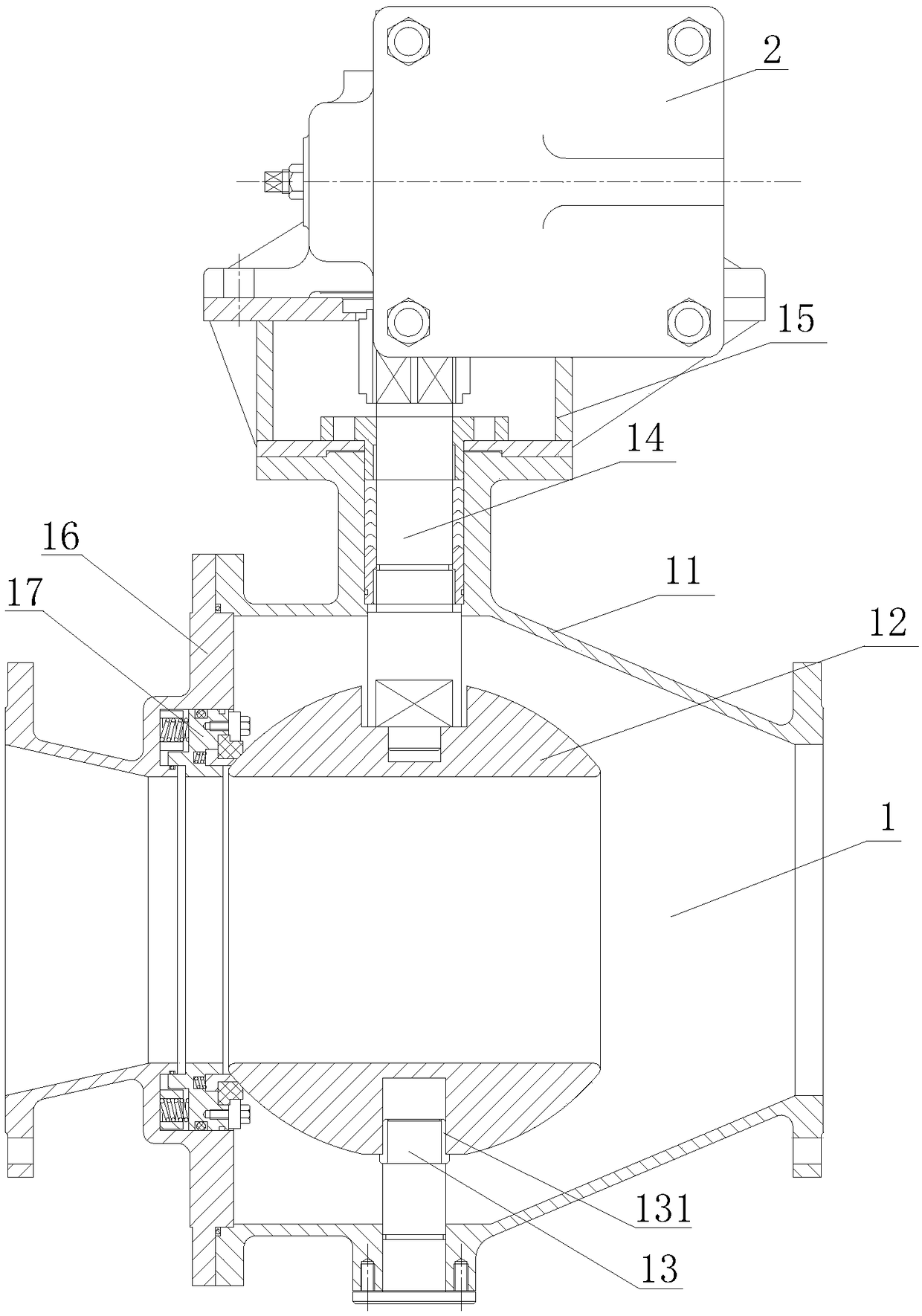
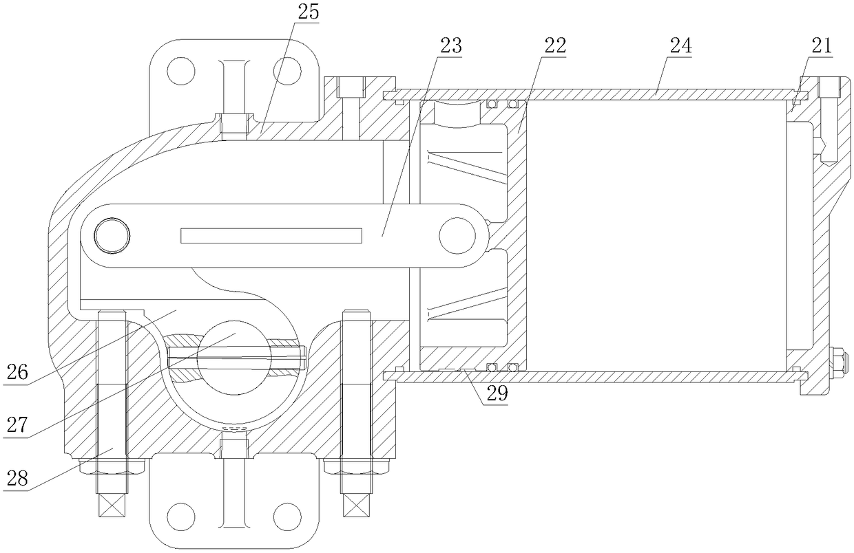
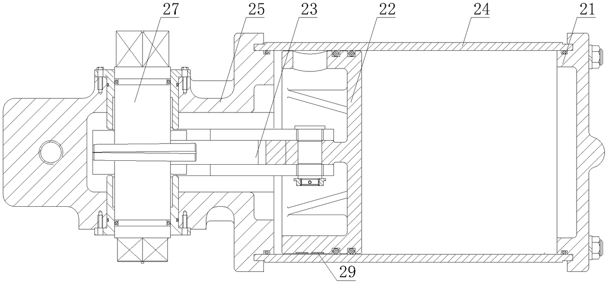
[0020] see Figure 1-4, a pneumatic ash unloading ball valve, including a ball valve body 1 and a pneumatic device 2, the pneumatic device 2 drives the ball valve body 1 to work to realize the opening and closing function of the entire pneumatic ash unloading ball valve, the pneumatic device 2 is installed above the ball valve body 1, and the pneumatic The device 2 is movably connected with the ball valve body 1, and the pneumatic device 2 includes a cylinder ...


PUM


Abstract

The invention discloses a pneumatic cinder ball valve, comprising a ball valve body and a pneumatic device. The pneumatic device comprises a cylinder back cover, a piston, a connecting plate, a cylinder, an actuator housing, a crank, a rotating rod and an adjusting positioning screw. The ball valve body comprises a valve body, a ball body, a support column, a valve stem, a bracket, a valve cover and an automatic compensation device. A single-cylinder double action means is connected with a unique actuator. The piston adopts a wear-resistant guide ring, which not only improves the guiding of the cylinder, but also reduces the frictional resistance and wearing of the piston, thereby improving the sealing performance. Multiple self-lubricating wear-resistant bushings are used throughout a rotation process to reduce the friction coefficient. The valve opens and closes quickly, accurately and flexibly. The ball body inside the valve body adopts a shaft-supporting structure, which reduces the operating torque of the ball valve and enhances the sealing reliability. Displacement of the ball body after being pressed can be prevented, and influence of pressure of the medium can be avoided. The automatic compensating device adopts a combination of soft and hard laminated sealing, and has the dual advantages of metal hard sealing and elastic sealing.

Description

technical field [0001] The invention relates to the technical field of pneumatic valves, in particular to a pneumatic ash unloading ball valve. Background technique [0002] The pneumatic ash unloading ball valve is a ball valve equipped with a pneumatic actuator, and the pneumatic ash unloading ball valve is evolved from a globe valve. It has the same action of rotating 90 degrees, but the difference is that the cock body is a sphere with a circular through hole or channel passing through its axis. Pneumatic ash unloading ball valve is generally composed of valve body, ball, valve seat, valve stem, bracket, pneumatic drive device and other components. However, the ordinary pneumatic ash unloading ball valve cannot be directly installed on the pipeline of the blast furnace ash unloading device in the metallurgical system, because the pulverized coal cinder is granular, has high hardness and is accompanied by humidity. The sealing structure cannot fully ensure the sealing p...

Claims


Application Information

Patent Timeline
IPC IPC(8): F16K5/06F16K5/20F16K31/122
CPCF16K5/061F16K5/201F16K31/122
Inventor 吴金龙方桂荣吕育壮
Owner 高昂
Learn More