
Plunger control system for well

A control system and plunger technology, applied in wellbore/well components, production fluid, measurement, etc., can solve problems such as judgment or measurement being in a blank state, optimize production process and system, avoid noise impact, and improve production process the effect of the system

Pending Publication Date: 2019-01-15
XIAN ANCN INTELLIGENT INSTR
View PDF0 Cites 6 Cited by
  • Summary
  • Abstract
  • Description
  • Claims
  • Application Information

AI Technical Summary

Problems solved by technology

[0003] In the prior art, the plunger gas lift drainage gas recovery system is generally installed, and the energy of the plunger gas lift mainly comes from the high-pressure gas stored in the casing pipe; through the plunger gas lift drainage gas recovery, the bottom hole fluid can be effectively Excluded, but at present, technically, the judgment or measurement of the plunger lifting the liquid column has always been in a blank state

Method used


Image

  • Plunger control system for well
  • Plunger control system for well
  • Plunger control system for well

Examples


Embodiment Construction

[0033] In describing the present invention, it is to be understood that the terms "center", "upper", "lower", "front", "rear", "left", "right", "vertical", "horizontal", The orientations or positional relationships indicated by "top", "bottom", "inner", "outer", etc. are based on the orientations or positional relationships shown in the drawings, and are only for the convenience of describing the present invention and simplifying the description, rather than indicating or implying References to devices or elements must have a particular orientation, be constructed, and operate in a particular orientation and therefore should not be construed as limiting the invention. The terms "first" and "second" are used for descriptive purposes only, and cannot be understood as indicating or implying relative importance or implicitly specifying the quantity of indicated technical features. Thus, a feature defined as "first" and "second" may explicitly or implicitly include one or more of t...


PUM


Abstract

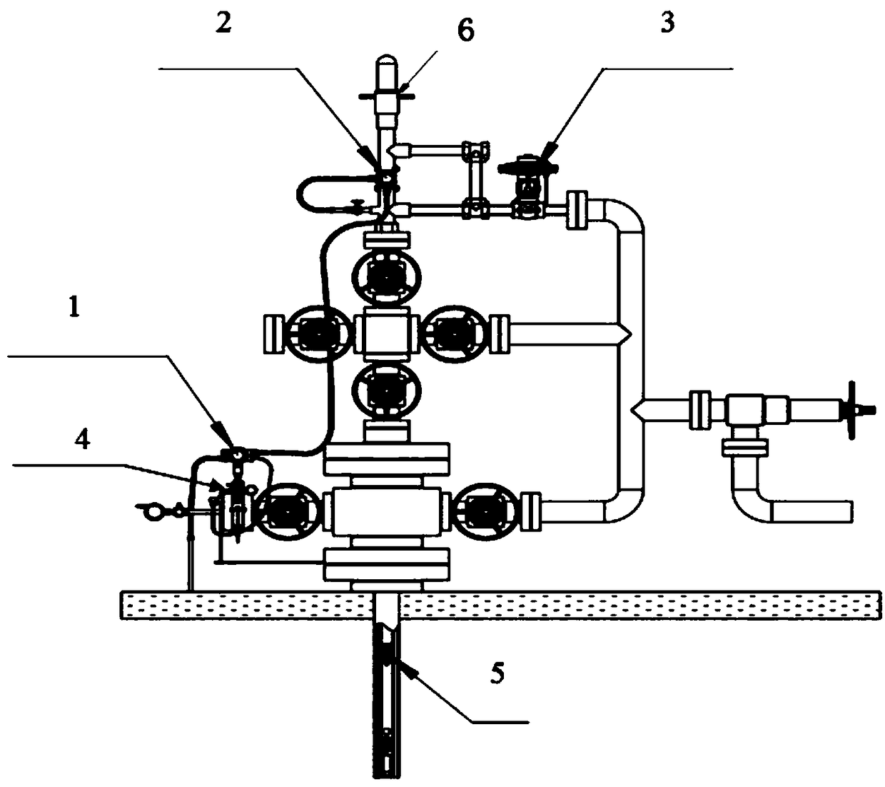
The present invention discloses a plunger control system for a well, and relates to the technical field of natural gas devices. The plunger control system employs devices such as a control header, anarrival sensor, a pneumatic film valve, a solenoid valve and an ACF two-phase flow flowmeter to integrally improve a current well plunger control system to achieve the accurate determination of the liquid slug, through adoption of the ACF two-phase flow flowmeter, single-well aerogenesis and liquid production capacity are effectively measured, the gaseous phase measurement precision can reach up to 1%, and the liquid phase measurement precision can reach up to 10%, and therefore, through accurate measurement of gas and liquid, the production process and the system can be better optimized.

Description

technical field [0001] The invention belongs to the technical field of natural gas equipment and relates to a wellhead device, in particular to a control system that provides a new technology approach for the stable production of complex gas fields with low pressure, low production, low abundance and strong heterogeneity. Background technique [0002] With the development of gas fields, the number of managed single wells is increasing year by year, and the number of water-producing gas wells is increasing, and the water production is gradually increasing. Due to the low single-well production of gas wells and poor liquid-carrying capacity, it is easy to cause fluid accumulation at the bottom of the well, which will adversely affect the production of gas wells, and the work of drainage and gas recovery has become increasingly prominent. [0003] In the prior art, the plunger gas lift drainage gas recovery system is generally installed, and the energy of the plunger gas lift m...

Claims


Application Information

Patent Timeline
Patent Type & Authority Applications(China)
IPC IPC(8): E21B43/12E21B47/00
CPCE21B43/122E21B47/00Y02P90/02
Inventor 刘涛王士兴史宁辉
Owner XIAN ANCN INTELLIGENT INSTR
Learn More