
Compound forming method of flow spinning and double-roller clamping spinning

A technology of flow spinning and compound forming, which is applied in the field of compound forming of flow spinning and double-roller clamping spinning, to achieve obvious economic benefits, high forming accuracy and production efficiency, and avoid repeated clamping and positioning

Active Publication Date: 2019-01-15
XI AN JIAOTONG UNIV
View PDF7 Cites 7 Cited by
  • Summary
  • Abstract
  • Description
  • Claims
  • Application Information

AI Technical Summary

Problems solved by technology

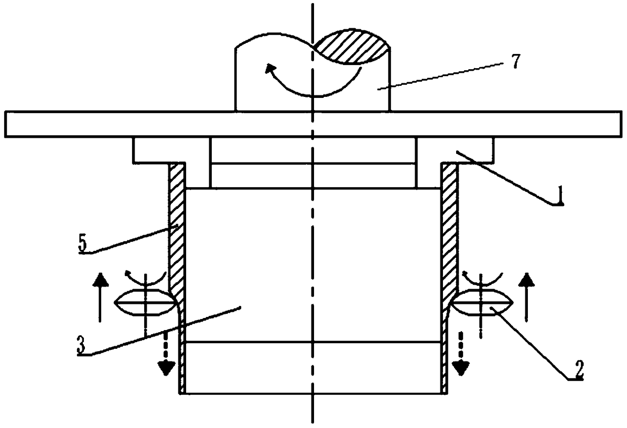
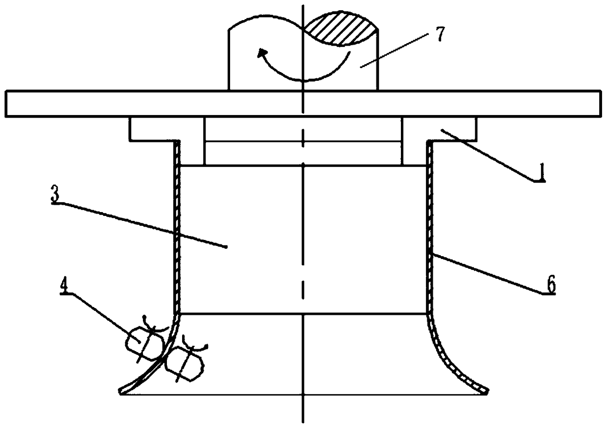
[0003] In order to overcome the above-mentioned shortcomings of the prior art, the object of the present invention is to provide a composite forming method of flow spinning and twin-roller clamping spinning, which combines flow spinning technology to manufacture thin-walled cylindrical parts and twin-roller clamping spinning technology The advantages of forming complex flange surfaces, at the same time, the entire composite forming process is formed on the same device at one time, there are no problems caused by welding, no need to repeat clamping and positioning, good process integration, stable forming, significantly improved forming accuracy and production efficiency

Method used


Image

  • Compound forming method of flow spinning and double-roller clamping spinning
  • Compound forming method of flow spinning and double-roller clamping spinning
  • Compound forming method of flow spinning and double-roller clamping spinning

Examples


Embodiment Construction

[0022] The present invention will be further described in detail below in conjunction with the drawings.

[0023] Reference figure 1 with figure 2 , The equipment used in a composite forming method of flow spinning and double-roll clamping spinning, including internal expansion clamping device 1, flow spinning wheel 2, core mold 3 and double-roll clamping spinning Roller 4; the thick-walled seamless tube blank 5 used is wall thickness t 0 , Inner diameter R 0 , Length L 0 Seamless pipe; the product to be formed is wall thickness t 1 , Inner diameter R 0 , Straight length L 1 , Flange length l 1 Of thin-walled rotary body parts with complex flange curved surface; the core mold 3 used is the outer diameter R 0 , Length L 0 Cylindrical parts.

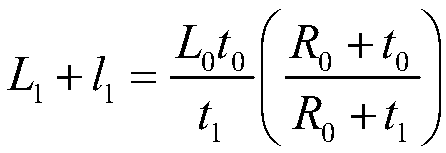
[0024] According to the flow spinning forming theory, the thin-walled rotating body parts with complex flange curved surfaces and thick-walled seamless tube blanks to be formed 5 satisfy:

[0025]

[0026] A composite forming method of flow spi...


PUM


Abstract

The invention provides a compound forming method of flow spinning and double-roller clamping spinning. The compound forming method of flow spinning and double-roller clamping spinning comprises the steps that firstly a thick wall seamless tube blank is clamped on a main shaft through an internal expansion type clamping device, and a core could is mounted in the thick wall seamless tube blank; thenrotating speed of the main shaft is set, and the thick wall seamless tube blank is rotated with the main shaft driven by the internal expansion type clamping device; counterflow spinning is carried out by adopting a spinning roller for flow spinning from the end, away from the internal expansion type clamping device, of the thick wall seamless tube blank, and a seamless thin walled cylinder pieceblank is formed; the spinning roller for flow spinning is replaced to a spinning roller for double-roller clamping spinning, double-roller clamping spinning forming is carried out on the seamless thin walled cylinder piece blank clamped by the spinning roller for double-roller clamping spinning, and a complex flange hook face is formed; and finally the core mould is taken out, clamping force of the internal expansion type clamping device is removed, and a well formed thin walled rotational part with the complex flange hook face is obtained. The compound forming method of flow spinning and double-roller clamping spinning has the advantages of flow spinning forming and double-roller clamping spinning forming, forming is in the same device at a time is achieved, and forming precision and production efficiency are obviously improved.

Description

Technical field [0001] The invention belongs to the technical field of forming thin-walled rotary parts, and specifically relates to a composite forming method of flow spinning and double-roller clamping spinning. Background technique [0002] With the rapid development of the manufacturing industry, the demand for thin-walled rotating body parts with complex flanges and curved surfaces is increasing. It is widely used in ventilation equipment such as fans in heating, ventilation and air conditioning systems, exhaust filters and internal combustion engines. Powerful draft hood, electrostatic precipitator bell mouth, high-voltage switch shield, aero engine extension and convergence section. The existing forming method of thin-walled rotary body parts with complex flange curved surfaces is to first obtain thin-walled cylindrical blanks by rolling and welding thin-walled plates, and then form the required complex flange curved surfaces by double-roller clamping and spinning. Among ...

Claims


Application Information

Patent Timeline
Patent Type & Authority Applications(China)
IPC IPC(8): B21D22/16
CPCB21D22/16
Inventor 范淑琴华毅赵升吨杜威郑臻皓
Owner XI AN JIAOTONG UNIV
Learn More