
A welding structure of a relay contact reed assembly

A welding structure and contact reed technology, applied in the field of welding positioning fixtures, special electrodes, and welding structures, can solve the problems of poor heat dissipation, large contact resistance, burnt reed components, etc., achieve accurate positioning, reduce tolerance range, The effect of enhancing thermal conductivity

Inactive Publication Date: 2019-01-11
GUIZHOU TIANYI ELECTRICAL
View PDF2 Cites 2 Cited by
  • Summary
  • Abstract
  • Description
  • Claims
  • Application Information

AI Technical Summary

Problems solved by technology

[0007] 3. The solder of the upper electrode and the lower electrode is tungsten-copper alloy, the contact resistance between the electrode and the welding wrap angle, and the contact surface of the contact reed is relatively large, and the heat dissipation is poor;
[0008] 4. The surface of the reed assembly after spot welding has burns, and the burns on the surface of the reed are more serious than the surface of the welded corner

Method used


Image

  • A welding structure of a relay contact reed assembly
  • A welding structure of a relay contact reed assembly
  • A welding structure of a relay contact reed assembly

Examples


Embodiment Construction

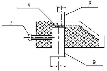
[0038] Such as Figure 4 , 5 As shown, a welding structure of a relay contact reed assembly, including a reed assembly 4, a positioning fixture 5, an adjustment screw 7, an insulating sheet 10, an upper electrode assembly 11 and a lower electrode assembly 12;

[0039] A reed assembly limit groove 4.1 is provided in the positioning fixture 5, which can ensure that the parallelism between the welding wrap angle and the side of the contact reed and their two side edges are flush after the assembly is welded;

[0040] The reed assembly 4 adopts a structure in which the reed is at the bottom and the welding wrap angle is at the top in the positioning fixture 5, so as to increase the current conduction and heat conduction area between the end face of the lower electrode and the surface of the reed, so that it is the upper electrode end face and the welding wrap angle of the product. 3 to 4 times of the diversion area, so that the welding heat is more concentrated on the welding wra...


PUM


Abstract

The invention relates to a welding structure of a relay contact reed assembly, comprising a reed assembly, a positioning fixture, an adjusting screw, an insulating sheet, an upper electrode assembly and a lower electrode assembly. A limit groove of the spring assembly is arranged in the positioning fixture. The reed assembly adopts the structure the the reed is below and the wrapping angle is above in the positioning fixture. After welding, each position dimension requirement of the product reed assembly meets the requirements of the process technology, and the welding wrapping angle is good in parallelism with the contact reed. The adhesion between the welding piece and the electrode head is greatly improved. After the welded reed assembly is loaded into the product, the technical parameters of the product meet the requirements of the process technology, and the mechanical aging, vibration, impact and other destructive tests are carried out on the product, and there is no product failure or reed fracture; accurate positioning, changing the main welding surface, increasing the contact area between the electrode and the reed, enhancing the thermal conductivity and electrical conductivity of the electrode welding positioning system, to meet the needs of mass production of products, while reducing the labor intensity of workers, improve labor efficiency.

Description

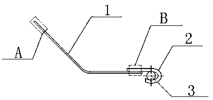
technical field [0001] The invention relates to a welding structure of a relay contact reed assembly, in particular to the use of a welding positioning fixture and a special electrode, and belongs to the technical field of electromechanical production process equipment. technical background [0002] The contact reed component is a very important component in the relay. In many small and precision sealed relays, the pure silver contact is directly riveted with the beryllium bronze reed as the current contact surface, and then welded with the zinc white copper strip to provide a certain contact pressure. The seat plate terminal is welded, and spot welding is usually used between the contact reed and the welding angle, such as figure 1 shown. The relative position and size of the parts in this component is directly related to the performance parameters of the whole product, and the welding quality at the junction of the welding wrap angle and the contact reed directly affects ...

Claims


Application Information

Patent Timeline
Patent Type & Authority Applications(China)
IPC IPC(8): H01H45/14
CPCH01H45/14
Inventor 潘华辉
Owner GUIZHOU TIANYI ELECTRICAL
Learn More