
Magnetic coupling structure for wireless charging of autonomous underwater vehicle and autonomous underwater vehicle system

An underwater vehicle and wireless charging technology, applied in transformer/inductor magnetic core, charging station, electric vehicle charging technology, etc., can solve the battery life problem, limit the development of autonomous underwater vehicles, and reduce the battery life in the charging dock , limited battery capacity and other issues, to achieve the effect of large power level, increased load, and small current ripple

Active Publication Date: 2019-01-11
HARBIN INST OF TECH AT WEIHAI +1
View PDF6 Cites 3 Cited by
  • Summary
  • Abstract
  • Description
  • Claims
  • Application Information

AI Technical Summary

Problems solved by technology

However, limited by the size and load capacity of autonomous underwater vehicles, the battery capacity is limited, and the battery life problem has always limited the further development of autonomous underwater vehicles.
In recent years, there have been some magnetic coupling devices used in wireless charging of autonomous underwater vehicles, but most of these magnetic coupling devices are single-phase magnetic coupling devices with low power levels; in addition, the input side current of single-phase wireless charging systems The ripple is large, and the large ripple will reduce the life of the battery in the charging dock

Method used


Image

  • Magnetic coupling structure for wireless charging of autonomous underwater vehicle and autonomous underwater vehicle system
  • Magnetic coupling structure for wireless charging of autonomous underwater vehicle and autonomous underwater vehicle system
  • Magnetic coupling structure for wireless charging of autonomous underwater vehicle and autonomous underwater vehicle system

Examples


Embodiment Construction

[0027] The present invention is described below based on examples, but the present invention is not limited to these examples. In the following detailed description of the present invention, some specific details are described in detail, and in order to avoid obscuring the essence of the present invention, known methods, procedures, procedures, and components are not described in detail.

[0028] Additionally, those of ordinary skill in the art will appreciate that the drawings provided herein are for illustrative purposes and are not necessarily drawn to scale.

[0029] Unless the context clearly requires, throughout the specification and claims, "comprises", "comprises" and similar words should be interpreted in an inclusive sense rather than an exclusive or exhaustive meaning; that is, "including but not limited to" meaning.

[0030] In the description of the present invention, it should be understood that the terms "first", "second" and so on are used for descriptive purp...


PUM


Abstract

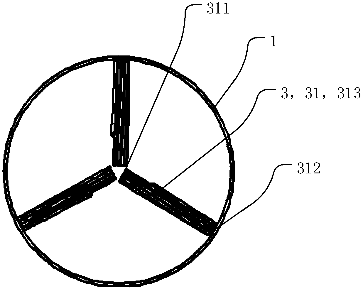
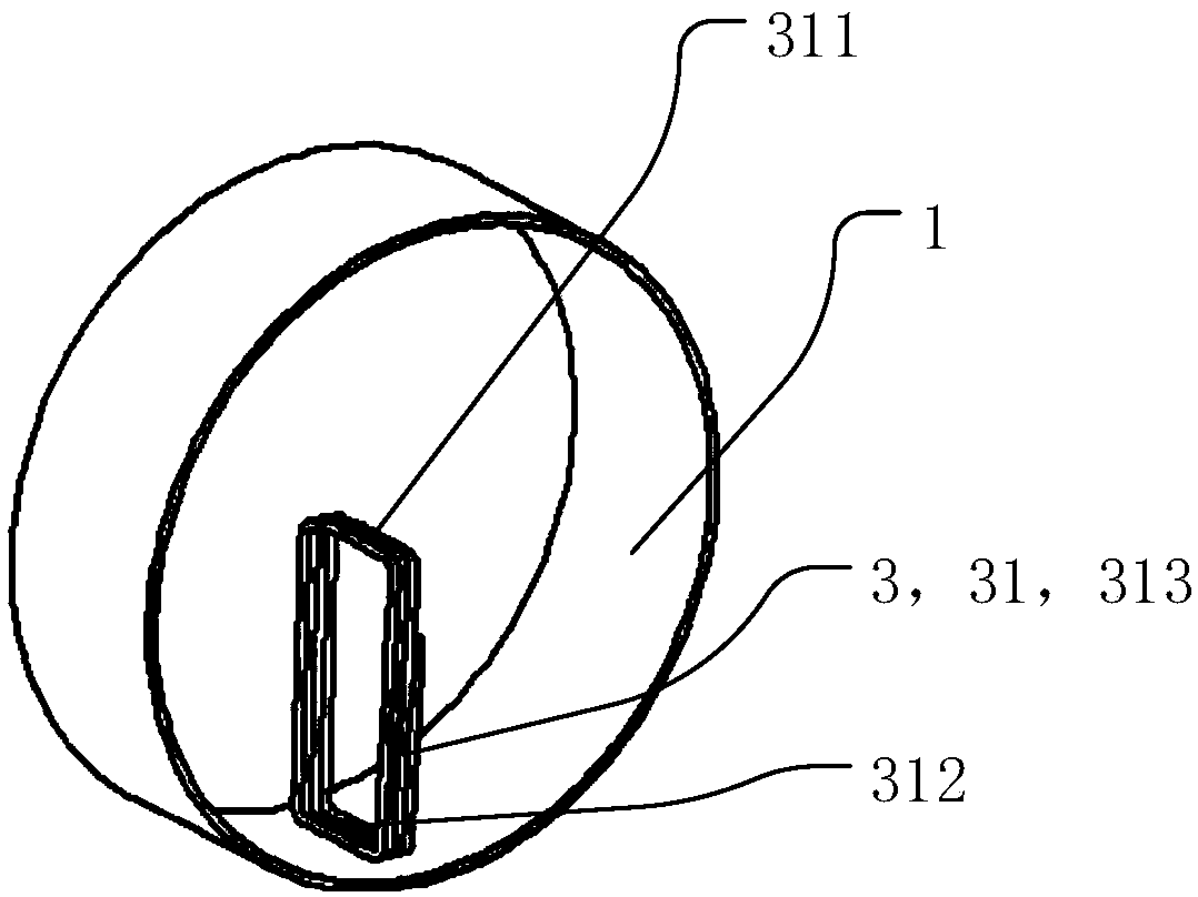
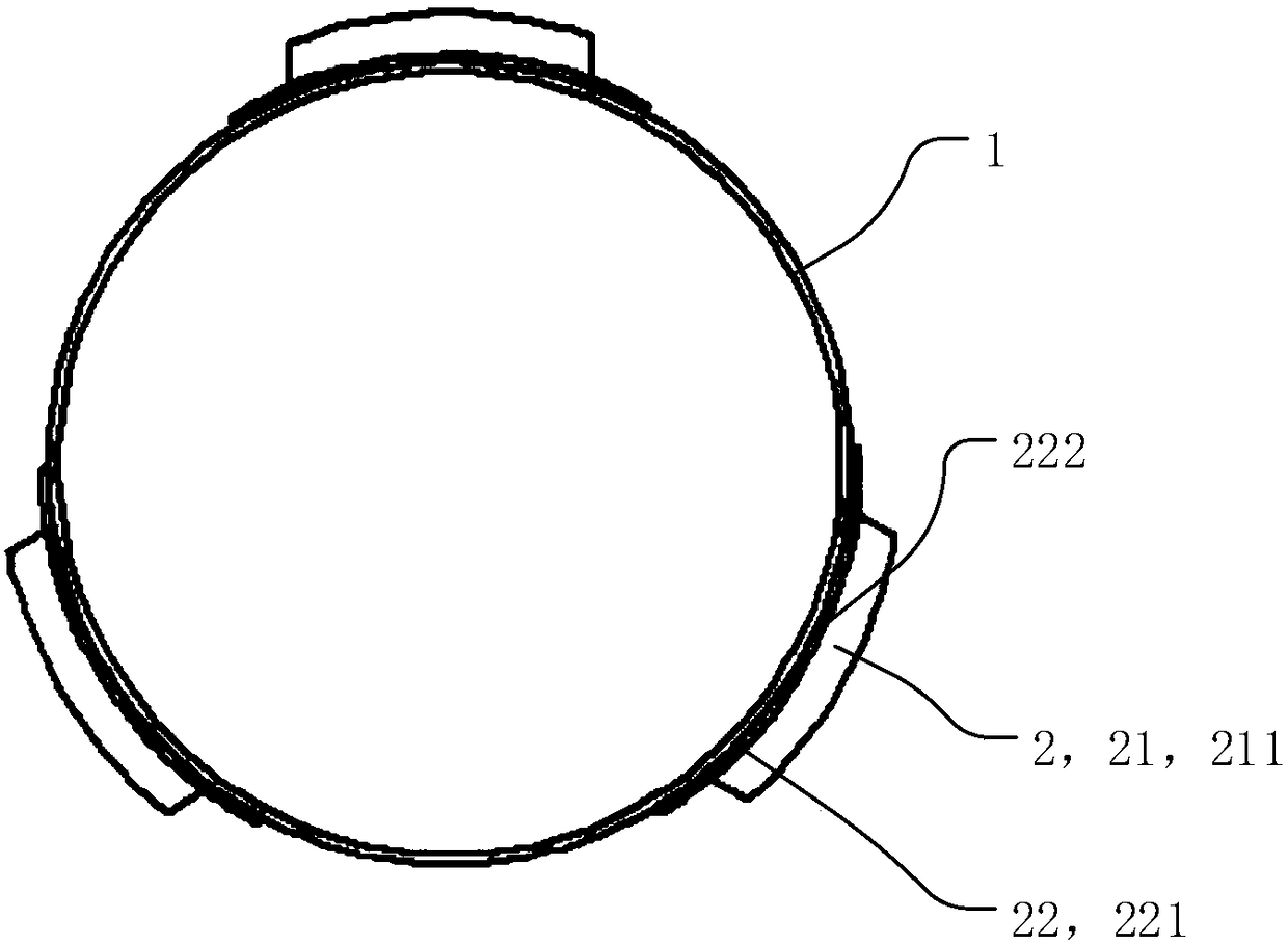
The invention discloses a magnetic coupling structure for wireless charging of an autonomous underwater vehicle and an autonomous underwater vehicle system, the magnetic coupling structure comprises atransmitting end arranged on a charging dock and a receiving end arranged on an autonomous underwater vehicle. The receiving end includes a receiving coil disposed along a radial direction of the autonomous underwater vehicle, including an inner end portion located at a radial center position of the autonomous underwater vehicle, an outer end portion located at an inner surface of the autonomousunderwater vehicle housing, and an intermediate portion located between the inner end portion and the outer end portion. The magnetic coupling structure for wireless charging of the autonomous underwater vehicle provided by the invention solves the problems of poor endurance and difficult charging of the autonomous underwater vehicle. The input side current ripple of the magnetic coupling structure is small, the transferable power level is large, and the battery life can be prolonged.

Description

technical field [0001] The invention relates to the technical field of wireless charging, in particular to a magnetic coupling structure for wireless charging of an autonomous underwater vehicle and an autonomous underwater vehicle system. Background technique [0002] As an important sea force, autonomous underwater vehicles are important tools for marine geological and landform exploration, marine environment observation, and marine resource exploration. strength. However, limited by the volume and load capacity of autonomous underwater vehicles, the capacity of batteries carried is limited, and the battery life problem has always limited the further development of autonomous underwater vehicles. At present, wireless charging technology is an ideal means to solve the endurance problem of autonomous underwater vehicles and achieve the goal of unattended. [0003] Unattended underwater autonomous vehicles will be equipped with one or more charging docks underwater. For ch...

Claims


Application Information

Patent Timeline
Patent Type & Authority Applications(China)
IPC IPC(8): H01F27/28H01F27/24H01F38/14H02J50/10B60L53/12
CPCH01F27/24H01F27/28H01F38/14H02J50/10Y02T10/70Y02T10/7072Y02T90/14
Inventor 蔡春伟武帅秦沐张言语刘金泉任秀云
Owner HARBIN INST OF TECH AT WEIHAI
Learn More